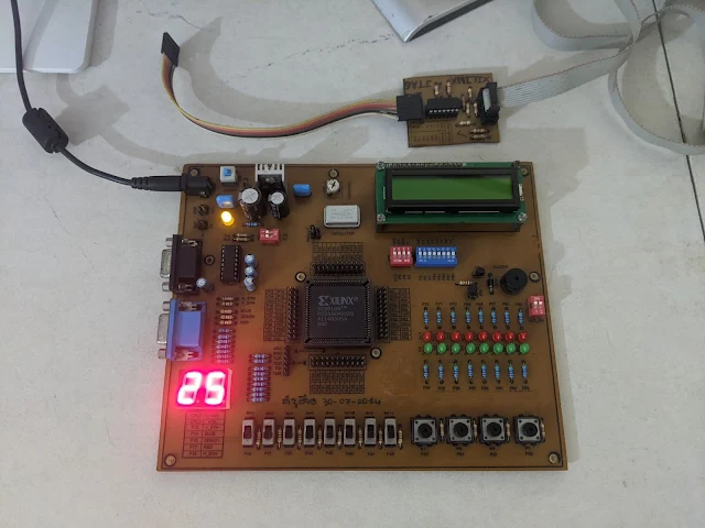
In this VHDL example, I use an XC95108 CPLD to read and convert two digits BCD variable to two distinct 7-Segment display. The input is an active low push button without de-bouncing or delay circuit. So the input press counting is unstable. I create two BCD variable to hold the 1'S and the 10's values.
 |
| Circuit Testing on the XC95108 Prototype Board |
The 7-Segment display is a 0.56 Inch individual digit command cathode type. This VHDL code create a digital counter that counts up to 99 before its rolls down to 0.
I use VHDL sequential code to make this circuit. It contains IF and CASE statements. I got this sample VHDL code from "Circuit Design with VHDL, Volnei A. Prdroni".
The XC95108, switches and 7-Segment display are connected as follow.
#PACE: Start of PACE I/O Pin Assignments
NET "CLK" LOC = "P53" ;
NET "DIGIT1<7>" LOC = "P37" ;
NET "DIGIT1<6>" LOC = "P35" ;
NET "DIGIT1<5>" LOC = "P21" ;
NET "DIGIT1<4>" LOC = "P33" ;
NET "DIGIT1<3>" LOC = "P34" ;
NET "DIGIT1<2>" LOC = "P36" ;
NET "DIGIT1<1>" LOC = "P24" ;
NET "DIGIT1<0>" LOC = "P23" ;
NET "DIGIT2<7>" LOC = "P32" ;
NET "DIGIT2<6>" LOC = "P18" ;
NET "DIGIT2<5>" LOC = "P17" ;
NET "DIGIT2<4>" LOC = "P26" ;
NET "DIGIT2<3>" LOC = "P25" ;
NET "DIGIT2<2>" LOC = "P31" ;
NET "DIGIT2<1>" LOC = "P20" ;
NET "DIGIT2<0>" LOC = "P19" ;
NET "RESET" LOC = "P48" ;
#PACE: Start of PACE Area Constraints
#PACE: Start of PACE Prohibit Constraints
#PACE: End of Constraints generated by PACE
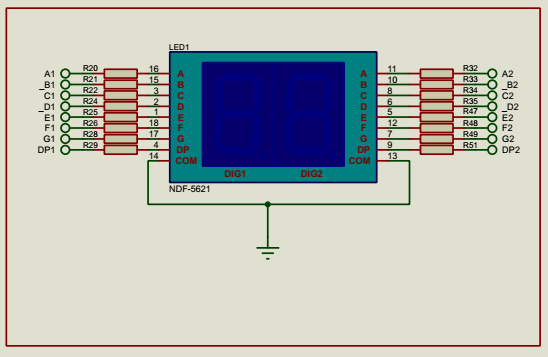
The two-digit 7-Segment display schematic is shown below.
 |
| Common Cathode 7-Segment Display |
 |
| XC9500 CPLD Reports |
This circuit design requires 45 macro cells. Click here to download its source file.
No comments:
Post a Comment