Introduction
As mentioned in previous post, configuring Timer/Counter0 module of ATMega16 to drive in counter mode the programmer doesn’t need to write a program routine to count external input pulse. The counter is automatically increase its content with the present of input pulse change.
Since counter mode is fast, the system can show its content on a multiplexing display without flickering. In this example of using Timer/Counter0 module, the system accept a number of input pulse from external device using its peripheral hardware inside. Its result will be displayed on a three-digit multiplexing display.
Hardware and Software Preparation
This programming example is solely experimented on a personal computer. Embedded controller’s program is written using embedded C in Atmel Studio 7 while its hardware experiment will be tested in Proteus simulator.
Hardware Preparation
Proteus is a good choice for electronics circuit design and simulation. Software simulation produces a nearby result to physical hardware test.
 |
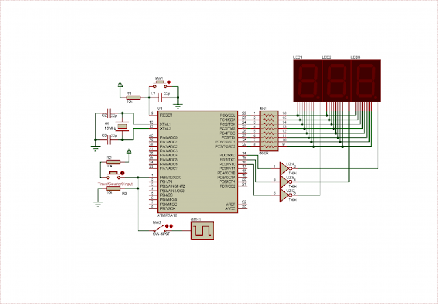
| Schematic diagram preparation for system simulation |
The user can choose another lower frequency of its crystal oscillator, but the delay function parameter must be properly set in software.
An optional square wave generator GEN1 supplies a variable high frequency. It’s enabled/disabled by a latched switch SW2.
Software Preparation
Software setting of counter mode of Timer/Counter0 peripheral is done within a few lines of code. Another routine is written to handle multiplexing display. This three-digits display made of some little more lines of code.
I created a label for delay function parameter. It’s “digitOn”, and it’s set to 5 (ms). it’s useful for code modification in later hardware test.
Proteus Simulation
Without spending time in physical hardware prototyping, the programmer can draw this example circuit in simulator. It also save a lot of time and budget of components purchasing.
 |
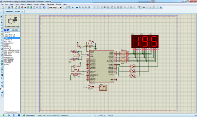
| Proteus simulation of this working example |
The result shown on this picture is 195 in decimal. the maximum counting of the 8-bit TCNT0 register is 0xFF or 255 in decimal. After it reached 255 it will roll back to 0 at next counting.
Creating A 16-bit Counter
We can get a 16-bit counting register from this 8-bit TCNT0 register by adding one more 8-bit register. An additional C unsigned 16-bit integer stores the total counting result up to 65536 counts.
Circuit Diagram Preparation
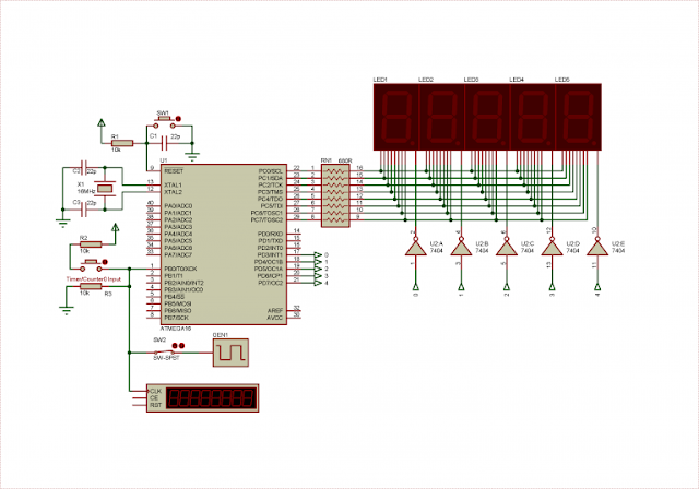
This optional programming example has some variation on its output display. It’s a five-digit multiplexing display that show a counting variable up to 65536 counts before it rolls back to 0.
 |
| Proteus VSM circuit diagram for hardware prototyping and simulation |
I added a counter timer virtual instrument to verify the counting result whenever the counter is supplied from a high speed square wave generator GEN1.
AVR GCC Code Preparation
I added an unsigned 8-bit character and another unsigned 16-bit integer to get a 16-bit counting variable in AVR GCC.
Since interrupt flag created by Timer/Counter0 Overflow (TOV0) is set whenever TCNT0 overflows and rolls back to 0, we test and clear this flag to update the 16-bit counting variable.
Unlike previous example of an 8-bit counter, this 16-bit counter needs a five-digit display. The need to add more lines of code to the program that drive this multi-digit multiplexing display. We will more embedded C codes in this example.
We will see its simulation result at the next section.
Simulation Result
This circuit diagram composes of a lot of components placement and breadboard wiring. Using a simulator could produce a comparable result to the one’s in physical hardware.
 |
| Simulation result in Proteus VSM of this working example |
Square wave generator GEN1 creates a frequency of 5kHz for this counter. Timer counter counts a nearby result with respect to the microcontroller counter. This microcontroller counting system reset its content whenever it reaches the maximum value of 65536 counts.
No comments:
Post a Comment