Saturday, November 27, 2021

PWM Pulse Steering in PIC16F887

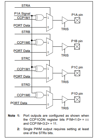
CCP1 can generate PWM signal up to 4 pins at the same time, by selecting CCP1M<3:2> = 11 and P1M<1:0> = 00. The Pulse Steering Control Register (PSTRCON) allow us to select any streering pin between P1A, P1B, P1C, and P1D.

PWM Pulse Steering in PIC16F887
 PSTRCON: PULSE STEERING CONTROL REGISTER
PWM Pulse Steering in PIC16F887
SIMPLIFIED STEERING BLOCK DIAGRAM

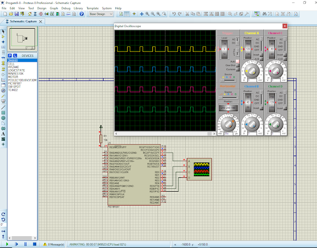
In this example, I use all PWM steering pins to generate the signal of 25% duty cycle.

void main() {
     TRISC=0x01;
     TRISD=0x00;
     OSCCON=0x70;
     CCP1CON=0x3C;
     PSTRCON=0x0F;             // steering output to P1<D:A>
     PR2=99;                   // Period is 50us
     CCPR1L=22;               // duty cycle is 25%
     T2CON=0x00;             // Timer2 Prescaler is 1:1
     TMR2=0;                   // clear timer 2
     T2CON.TMR2ON=1;          // Enable timer2
     PIR1.TMR2IF=0;             // clear flag
     while(PIR1.TMR2IF==0);     // wait until new cycles
}

I use simulator to test this program.
PWM Pulse Steering in PIC16F887
Program simulation

This system uses a 8MHz internal RC oscillator of PIC16F887.

No comments:

Post a Comment

Labels

ADC (10) Analog (14) Arduino (12) Atmega16 (19) Audio (2) AVR (20) Charger (1) Cortex-M0 (1) Counter (10) CPLD (25) Digital I/O (22) Display (34) EEPROM (2) Environment Sensor (1) esp8266 (2) Experiment Board (10) I2C (4) Interrupt (7) LCD (1) LDmicro (29) measurement and instrumentation (7) Microchip Studio (3) MikroC (1) One-Shot (3) OpAmp (1) PCB (31) PIC16 Microcontrollers (16) PIC16F877A (2) PIC16F887 MikroC (22) PLC (35) PWM (11) Regulator (1) RTC (2) Sensor (8) Shift Registers (5) SPI (5) Timer (34) UART (2) ultra-sonic sensor (1) USB (1) VHDL (21) xc8 (1) XC95108 (9) XC9536 (15) XC9572 (1) Xilinx (23) Xilinx ISE (22)