Sunday, July 25, 2021

Creating Gerber File Of The PCB Design In Proteus


About Proteus

Proteus VSM is an EDA software owns by Labcenter Electronics from the UK. It offers the the simulation of the analog, digital circuit using SPICE. Simulating the microcontroller/microprocessor is also a good option. It’s a paid software. However I share the license of this software with the company I’m working.

Beside the simulation in this software, the designer could create a circuit board design of the corresponding project. The circuit board design using Proteus takes a shorter time than other EDA software as I have been work with it for many years now. It has a lot of symbols and footprint library. The schematic and PCB design process is simple because we don’t any complex step.

Why Gerber ?

Gerber file format is a standard uses by the PCB industry. It contains the graphic of the design PCB such as copper layer, silk screen layer, drill size, etc.

The designer have to make this file to before the design is sent to the PCB manufacturer. However for a DIY PCB making, especially for the hobbyist, it’s not always need this file format. A single side PCB that will be fabricate by hand with a few amounts could be done by a simple toner transfer method, a silk screen process or a DIY dry film process.

Getting The Design Ready

I don’t show any detail of the circuit board design here because the article will take so long. Designing the circuit board process must be shown in a video tutorial.
Creating Gerber File Of The PCB Design In Proteus
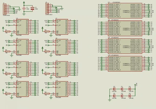
A Sample Schematic


Creating Gerber File Of The PCB Design In Proteus
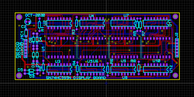
A Sample PCB

For most of the PCB design, the designer must very the design individually. It’s assumed that the project really work before starting the PCB design. As I have experienced the common mistake of the design is setting a right drill hole of the specific on-board components. 

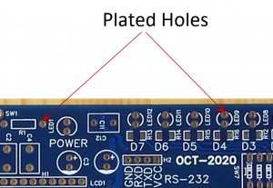
Using a service from the PCB manufacturer, the fabricated PCB must be at least a double-sided PCB to ease the soldering/assembling of the project. The drill hole always plated while it’s in manufacturing. Selecting a larger drill hole of a specific component doesn’t matter. However selecting a smaller drill hole of the component, the inserting doesn’t fit. The drill plated holes could be work again manually. But drilling the plated hole could make the disconnection of the circuit inter-connect. It makes trouble to the working project.


Creating Gerber File Of The PCB Design In Proteus
Plated holes of the fabricated PCB from manufacturer


Creating Gerber File


Each layer of the PCB has its own Gerber file. The overall design consists of many Gerber file. The file format is in text file that will be interpreted by software. For most common, the Gerber files are zipped in a single zip file.


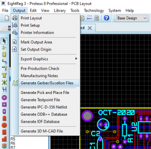
In Proteus PCB Layout, go to Output -> Generate Gerber/Excellon Files.
Creating Gerber File Of The PCB Design In Proteus
Generate Gerber Files

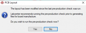
The pre-production checking prompt will display. We can ignore it by clicking NO.
 

Creating Gerber File Of The PCB Design In Proteus
Running or ignoring the pre-production check.

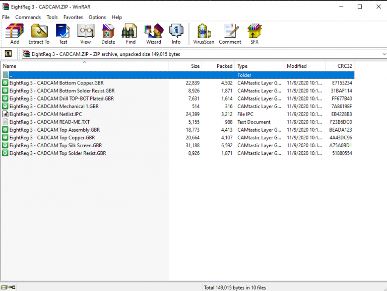
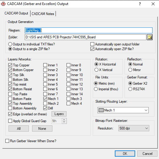
All layers in the design are ticked in the CAD/CAM Output. The user can select or deselect any layer. The Gerber files are zipped in one zip file.
Creating Gerber File Of The PCB Design In Proteus
CAD/CAM Output

 Click OK to create.

Creating Gerber File Of The PCB Design In Proteus
A created zip file of the Gerber files

This file will be uploaded to PCB manufacture website for ordering.

Putting An Order Of The Design

There are many PCB manufactures that we can put an order online. I have been a customer of PCBWay. It takes only a few days to get the PCB to my workplace after I put the order, and make payment.


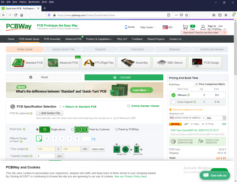
On the manufacturer quick online order page, upload your design and get quote.
Creating Gerber File Of The PCB Design In Proteus
Quick Order Page Of PCBWay

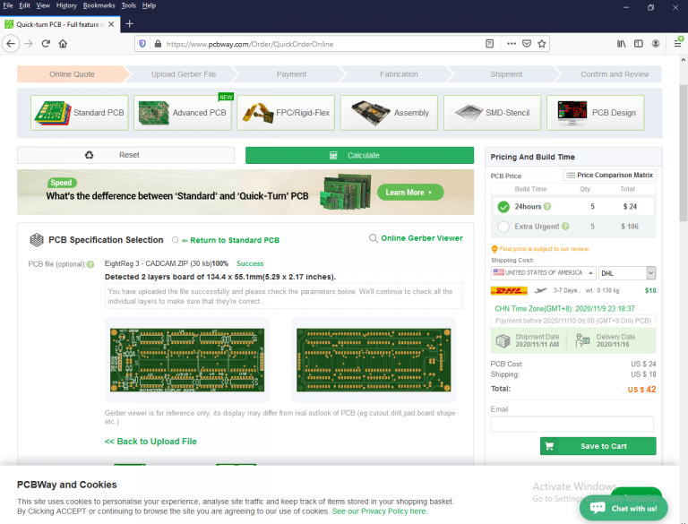
Click on Add Gerber File to select and upload the zipped Gerber files that has just created by Proteus.


Creating Gerber File Of The PCB Design In Proteus
An uploaded Gerber format

The page will automatically determine the dimension and the number of layers. What the user select are,

  • the thickness of the board
  • color of solder mask and silk screen
  • copper thickness
  • pad plating, etc.

I don’t list them all here because it’s the choice of customer. As I have ordered from this manufacturer, the processing time is less than 24 hours to complete. The delivery time takes only one day to arrive at my warehouse.
Wednesday, July 21, 2021

Getting Started With C In Atmel Studio 7 Using ATMega16


An Overview Of ATMega16

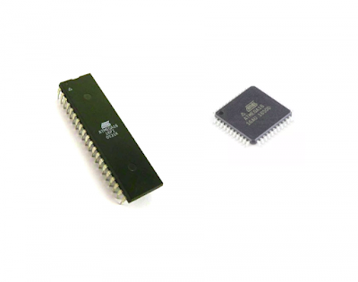
ATMega16 is an 8-bit microcontroller built using RISC architecture bases on flash technology. Its original manufacture Atmel, now become a part of the Microchip Technology since 2016. However those AVR microcontroller series are still continuous to develop. 

Getting Started With C In Atmel Studio 7 Using ATMega16
The ATMega16 in DIP and SMD Package

ATMega16 has three storage memory parts:

  • Flash memory, or program memory for program storage (firmware) of 16 kBytes with ISP feature.
  • 1 kBytes of general purpose registers
  • 512 Bytes of SRAM

The CPU could clock up to 16 MHz when it’s supplied about 5 V, yield the executing speed 16 MIPS.

It comes with 40-pin DIP version and also a SMD version.

Microcontroller communication interfaces built inside this device:

  • Two-wire Serial Interface – TWI
  • Serial Peripheral Interface – SPI
  • Universal Synchronous Asynchronous Receiver Transmitter – USART

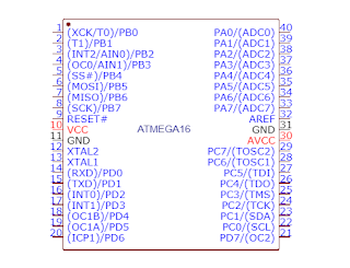
Digital input output (I/O) is divided into four 8-bit ports:

  • PORTA
  • PORTB
  • PORTC
  • PORTD


Getting Started With C In Atmel Studio 7 Using ATMega16
Pin Diagram of the most common used ATMega16 40-Pin DIP Package

They are bi-directional read/write port register.


Analog input channels are multiplexed with those digital I/O. The Analog to Digital Converter (ADC) yields an 10-bit resolution available between its 8 input channels. The ADC gain is select-able. 

Analog output, Pulse Width Modulation (PWM) modules generate an analog output voltage via their output compare pins. They work with the three timer modules inside this MCU.

Interrupt is a effective way to notifies the MCU. In ATMega32 the interrupts are the external interrupt and the peripheral interrupts triggered by its inside peripheral modules.

Programming the ATMega16 AVR

The assembly language is design with the target MCU with the description of the internal hardware operations. Currently most the 8-bit MCU is programmed using the C language targeting a specific architecture.

Atmel (now becomes a part Microchip Technology) develop and IDE, Atmel Studio enable the programmer the code their AVR and AVR32 products for free. It bases on the AVR GCC. However this IDE supports the assembly, C and C++ programming languages. Now, in 2020 the current version is Atmel Studio 7.


I know a few third party compiler for the AVR MCU series:

  • MikroC for AVR
  • CodeVision AVR
  • IAR Embedded Workbench for AVR

Some of them offer a free version of their compiler with a limit coding. But for a full features access of the resources the programmers need to pay for a license.

For me I prefer Atmel Studio for my programming and project developments.

Getting Started With Atmel Studio 7

The Atmel Studio support both a low level and a high level C/C++ coding. For most programmers, they like to program in C due to its ease of coding density.

To get start the programmer need to download the Atmel Studio IDE from the Microchip Technology website, and install it on their PC.

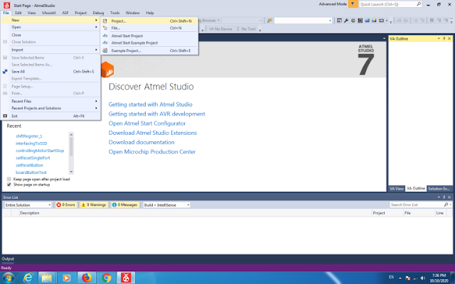
After the installation, open the IDE and make a new project.


Getting Started With C In Atmel Studio 7 Using ATMega16
Make a new project

Getting Started With C In Atmel Studio 7 Using ATMega16
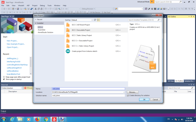
Select GCC Executable Project, its location and name


Getting Started With C In Atmel Studio 7 Using ATMega16
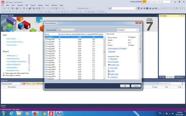
Select the ATMega16 as a target device

Getting Started With C In Atmel Studio 7 Using ATMega16
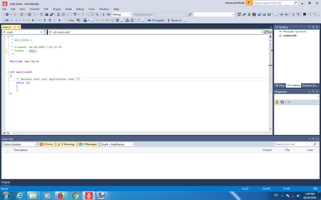
Then coding window will appeared.


Getting Started With C In Atmel Studio 7 Using ATMega16
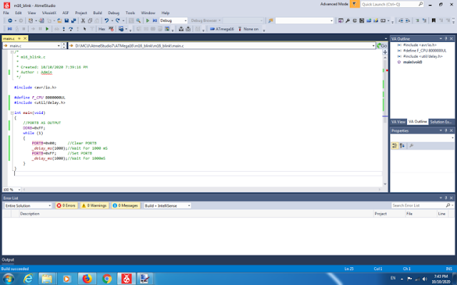
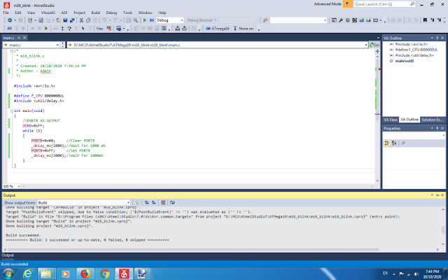
Let write a sample code as shown in this picture. This code blink PORTB of the ATMega16.

Getting Started With C In Atmel Studio 7 Using ATMega16
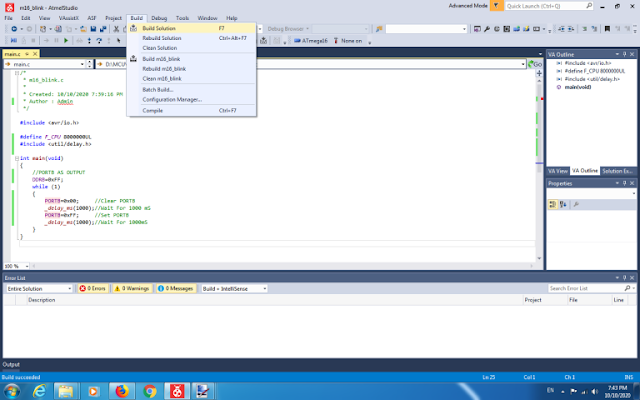
Now it’s ready to build the project

Getting Started With C In Atmel Studio 7 Using ATMega16
An error-free coding creates the binary file for the target MCU to execute.


AVR C source code in Atmel Studio 7:

/*
 * m16_blink.c
 *
 * Created: 10/10/2020 7:39:16 PM
 * Author : Admin
 */ 

#include <avr/io.h>

#define F_CPU 16000000UL
#include <util/delay.h>

int main(void)
{
    //PORTB AS OUTPUT
    DDRB=0xFF;
    while (1) 
    {
        PORTB=0x00;        //Clear PORTB
        _delay_ms(1000);//Wait For 1000 mS
        PORTB=0xFF;        //Set PORTB
        _delay_ms(1000);//Wait For 1000mS
    }
}

Within the code above the label F_CPU is a parameter used by the delay.h file below the delay is created.

The schematic below is full assembling symbol for the breadboard system assembling.


Schematic diagram for this example to wire on the breadboard

The Hardware Test

Development Board and ISP Programmer

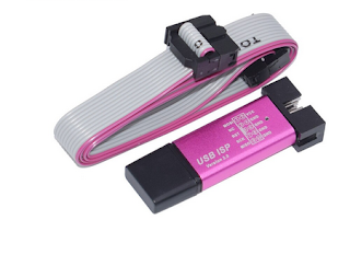
I use my own development board I designed/assembled. The code is written to fit this board. However, it doesn’t come with a pre-burned boot-loader nor an on-board block of ISP. I putted an ISP header, compatible to the USBasp USB-based ISP programmer. The USBasp is open-source. We can make it by hand, or buying from any store for a few Dollars.

Getting Started With C In Atmel Studio 7 Using ATMega16


I also made my own one using the ATMega8 with a dozen of components. The host PC side ISP software is widely available. I have been using many software that the USBasp ISP hardware. Currently, I switched to a GUI version of AVRdude. This software supports many ISP hardware for the Microchip AVR devices.

The AVRdude

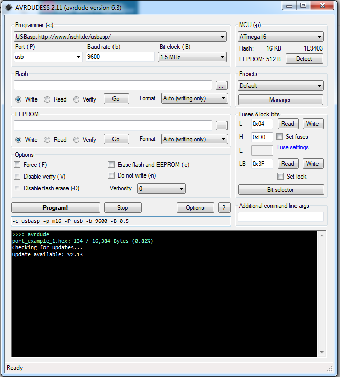
As mentioned earlier, the AVRdude has a user-friendly GUI version that made by an author.


Getting Started With C In Atmel Studio 7 Using ATMega16
A GUI version of the AVRdude

For a first use of the USBasp ISP programmer, the user need to install the USB driver of this USB programmer. Previously, I used Windows 7 32-bit OS. Installing the USBasp driver on this OS is easy because the driver file comes with downloaded zip file from the USBasp website.


Currently, I migrate my computer’s OS to Windows 7 64-bit and up to Windows 10 64-bit. Installing the USB driver with those conventional driver file is very hard, and doesn’t work for me. I saw a solution from the online forum. It’s the Zadig, USB driver installation.

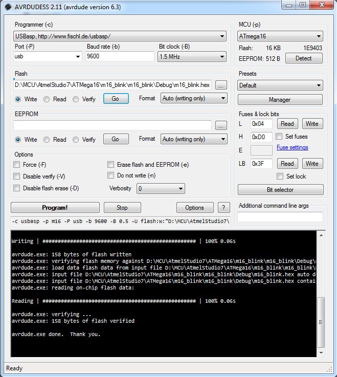
Plug your USBasp to the host PC operates the Windows7/10 64-bit, and install the USB driver with an appropriate one’s. Then open the AVRdude to test the device reading/writing. 

Getting Started With C In Atmel Studio 7 Using ATMega16
A successful writing to the ATMega16


After this successful hex file uploading let see the real hardware test.


Getting Started With C In Atmel Studio 7 Using ATMega16
A program test on development board

Click here to download this example. To get started coding the ATMega16 using C in Atmel Studio 7, see this video.


Labels

ADC (10) Analog (14) Arduino (12) Atmega16 (19) Audio (2) AVR (20) Charger (1) Cortex-M0 (1) Counter (10) CPLD (25) Digital I/O (22) Display (34) EEPROM (2) Environment Sensor (1) esp8266 (2) Experiment Board (10) I2C (4) Interrupt (7) LCD (1) LDmicro (29) measurement and instrumentation (7) Microchip Studio (3) MikroC (1) One-Shot (3) OpAmp (1) PCB (31) PIC16 Microcontrollers (16) PIC16F877A (2) PIC16F887 MikroC (22) PLC (35) PWM (11) Regulator (1) RTC (2) Sensor (8) Shift Registers (5) SPI (5) Timer (34) UART (2) ultra-sonic sensor (1) USB (1) VHDL (21) xc8 (1) XC95108 (9) XC9536 (15) XC9572 (1) Xilinx (23) Xilinx ISE (22)