Tuesday, June 28, 2022

LED Blinking using TimerOne Library of Arduino

The Arduino Uno is typically powered by the Atmega328. It has Timer/Counter1 module to make a timing or counting process. To access this timer module, the programmer needs to install a library for timer1. This timer library can be used to create a timing delay, or a PWM signal, etc.
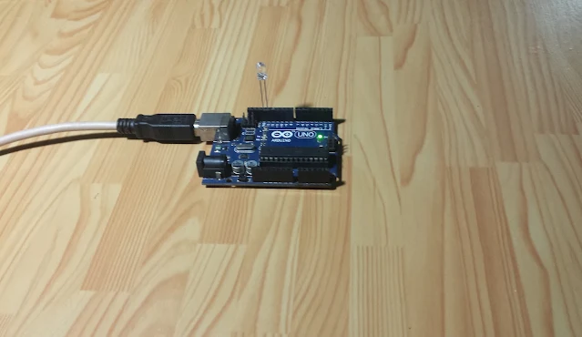
Blinking an LED using Timer1 Library of Arduino
Running program on board

In this example, I use this timer library to blinking an LED. This library has a timer interrupt for a specific period. So we can use its timer interrupt to create a timing tick. Using this feature the main program loop doesn't need to wait for any duration. It has an advantage rather than using the Millis(), or delay function library of the Arduino.

  1. #include <TimerOne.h>
  2.  
  3. void setup(){
  4. pinMode(13,OUTPUT);
  5. //set timer 1 duration to 250ms
  6. Timer1.initialize(250000);
  7. //Interrupt Handling
  8. Timer1.attachInterrupt(blinkLed);
  9. }
  10.  
  11. void loop(){
  12.  
  13. }
  14.  
  15. bool state=false;
  16. void blinkLed(){
  17. digitalWrite(13,state);
  18. state^=1;
  19. }

I don't draw its schematic here because this example use only the BUILD-IN LED of the Arduino Uno board. 

Click here to download this example.
Monday, June 27, 2022

Arduino and DS18B20 Temperature Controlling Example

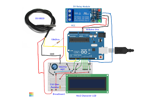
 A temperature controller can be found anywhere in the market at low cost. However we can create it one using an analog circuit, or even a programmable device. Here I create an Arduino-based temperature controller using some components:

  1. An Arduino Uno board
  2. A DS18B20 temperature sensor
  3. A 5V relay module
  4. A character LCD with some other components and accessary.
Arduino and DS18B20 Temperature Controlling Example
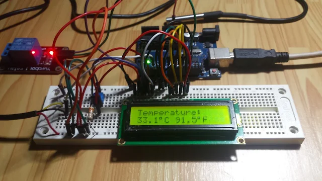
Circuit prototyping on breadboard

The controller request and get temperature data from DS18B20 in degree Celsius. The display show either Celsius and degree Fahrenheit. It updates the data for every 5 seconds. I set in program for a condition for the temperature above 30 degree Celsius. Whenever it's true an output relay connects to pin 13 will turn on.

Arduino and DS18B20 Temperature Controlling Example
Schematic Diagram

I use DallasTemperature.h file due to its simplicity. 

  1. #include <OneWire.h>
  2. #include <DallasTemperature.h>
  3. #include <LiquidCrystal.h>
  4.  
  5. //LCD Connection RS EN D4...D7
  6. LiquidCrystal lcd(7,8,9,10,11,12);
  7.  
  8. OneWire oneWire(4);
  9.  
  10. DallasTemperature sensors(&oneWire);
  11.  
  12. //Relay Output Pin
  13. const int relay=13;
  14.  
  15. void setup(){
  16. pinMode(relay,OUTPUT);
  17. //Start up the 1-Wire Library
  18. sensors.begin();
  19. lcd.begin(16,2);
  20. lcd.print("ds18B20 Example");
  21. delay(3000);
  22. lcd.clear();
  23. }
  24.  
  25. float getC,getF;
  26.  
  27. void loop(){
  28. //Send the command to get Temperature
  29. sensors.requestTemperatures();
  30. getC=sensors.getTempCByIndex(0);
  31. getF=DallasTemperature::toFahrenheit(getC);
  32.  
  33. if(int(getC)>=30) digitalWrite(relay,HIGH);
  34. else digitalWrite(relay,LOW);
  35.  
  36. lcd.home();
  37. lcd.print("Temperature: ");
  38. lcd.setCursor(0,1);
  39. lcd.print(String(getC,1)+char(223)+"C"+" "+String(getF,1)+char(223)+"F");
  40. delay(5000);
  41. }

Click here to download its source file.


Friday, June 24, 2022

Arduino Uno DS3231 RTC and Character LCD Example

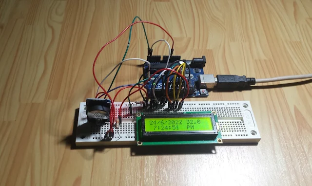
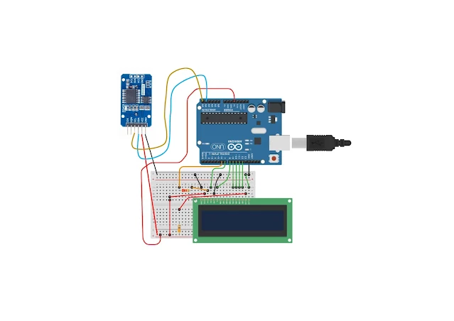
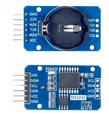
In previous post, I showed an example of using a character LCD with Arduino Uno. Here I will add a Real Time Clock (RTC) module, that it's powered by the DS3231 real time clock chip. This chip contain timing data that store in its internal RAM. Optionally it contain a temperature sensor chip that tell us the current device temperature.

Arduino Uno DS3231 RTC and Character LCD Example
An RTC module that contain a DS3231 and an EEPROM

In this example, the Arduino Uno will read current timing from DS3231. That timing will display on the character LCD.

Arduino Uno DS3231 RTC and Character LCD Example
Program Example

The first line are Date/Month/Year and the device temperature in degree Celsius. The second line are the current time with AM/PM indication.

Arduino Uno DS3231 RTC and Character LCD Example
Schematic

I use PWM of the Arduino to adjust the LCD contrast Vo. The PWM pin 6 of Arduino connects to the LCD Vo pin via a 2.2 kOhm resistor. The PWM duty cycle is 50. 

The Arduino source code is only a little.

  1. //Arduino LCD and DS3231 RTC Example
  2. #include <LiquidCrystal.h>
  3.  
  4. #include <DS3231.h>
  5. #include <Wire.h>
  6.  
  7. LiquidCrystal lcd(7,8,9,10,11,12);
  8. DS3231 Clock;
  9. bool Century = false;
  10. bool h12,PM;
  11. String dut;
  12.  
  13. void setup(){
  14. //LCD Contrast
  15. pinMode(6,OUTPUT);
  16. analogWrite(6,50);
  17. //Start I2C
  18. Wire.begin();
  19. lcd.begin(16,2);
  20. lcd.print("Arduino LCD and");
  21. lcd.setCursor(0,1);
  22. lcd.print("DS3231 Example");
  23. delay(3000);
  24. lcd.clear();
  25. }
  26.  
  27. void loop(){
  28. //Check PM or AM
  29. if(PM) dut="PM";
  30. else dut="AM";
  31.  
  32. //Date
  33. lcd.setCursor(0,0);
  34. lcd.print(String(Clock.getDate(),DEC)+"/"+String(Clock.getMonth(Century),DEC)
  35. +"/"+"20"+String(Clock.getYear(),DEC)+" "+String(Clock.getTemperature(),2));
  36.  
  37. //Time
  38. lcd.setCursor(0,1);
  39. lcd.print(String(Clock.getHour(h12,PM),DEC)+":"+String(Clock.getMinute(),DEC)
  40. +":"+String(Clock.getSecond(),DEC)+" "+dut);
  41. }

Click here to download its source file.

Wednesday, June 22, 2022

Arduino and 16x2 Character LCD Example

In this programming example, I will show how to interface a 16x2 character LCD with the Arduino Uno board. Arduino is very popular for electronic hobbyist, engineering projects, and DIY electronics, etc. A character LCD is very popular, low cost, and it's very easy to program. However this type of LCD use a parallel port interface that requires many wires. It's 8-bit wide, but the programmer can use only 4-bit mode to cut down the total in-circuit wires.

Arduino and 16x2 Character LCD Example
A running program on my prototyping board

In this example, I also use serial port to send character data to the Arduino Uno Board. Finally those data will send to the character LCD.

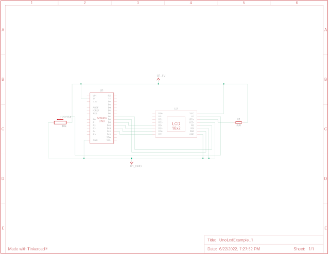
Arduino and 16x2 Character LCD Example
Schematic Diagram

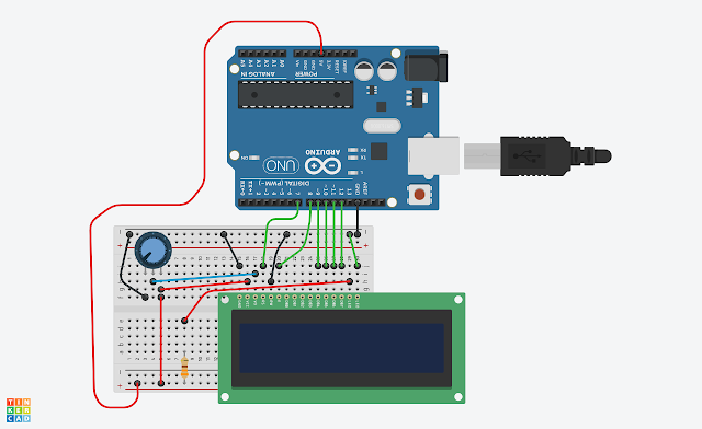
We can also use tinkercad to draw and simulate this example using web browser.

Arduino and 16x2 Character LCD Example
Circuit View

Arduino Source Code:

  1. #include <LiquidCrystal.h>
  2.  
  3. LiquidCrystal lcd(7,8,9,10,11,12);
  4.  
  5. void setup(){
  6. Serial.begin(9600);
  7. lcd.begin(16,2);
  8. lcd.print("Arduino Uno LCD");
  9. lcd.setCursor(0,1);
  10. lcd.print("Example");
  11. delay(3000);
  12. lcd.clear();
  13. lcd.blink();
  14. }
  15.  
  16. void loop(){
  17. if(Serial.available()>0){
  18. char temp = Serial.read();
  19. lcd.print(temp);
  20. }
  21. }

Click here to download this example.

Thursday, June 16, 2022

Programming All External Interrupt Sources of Atmega16

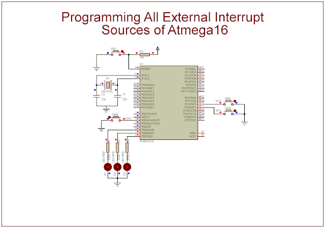
In previous post, I show a simple programming example of INT0. As it's already stated, the Atmega16 has up to 3 external interrupt sources. In this example, I use all its external interrupt sources, the INT0, the INT1, and the INT2.

I select the low logic level of these interrupt source to trigger the ISR. Whenever any interrupt occurs, its corresponding output LEDs will toggle its logic state. The output LEDs are PB5, PB6, and PB7.

Programming All External Interrupt Sources of Atmega16
Program simulation

Source Code:

 1
 2
 3
 4
 5
 6
 7
 8
 9
10
11
12
13
14
15
16
17
18
19
20
21
22
23
24
25
26
27
28
29
30
31
32
33
34
35
36
37
38
39
40
41
42
43
44
45
46
47
48
49
50
51
52
/*
 * atmega16AllExtIntEx.c
 *
 * Created: 6/10/2022 7:06:23 PM
 * Author : Admin
 */ 

#include <avr/io.h>

#include <avr/interrupt.h>

int main(void)
{
	
	//PD2 and PD3 Input
	DDRD&=~(1<<2);
	DDRD&=~(1<<3);
	//Turn on PD2 and PD3 high
	PORTD|=(1<<2)|(1<<3);
	//PortB output
	DDRB=0xFF;
	//PB2 input
	DDRB&=~(1<<2);
	//Turn PB2 high
	PORTB|=(1<<2);
	//Enable INT0...2 request
	GICR|=(1<<INT0)|(1<<INT1)|(1<<INT2);
	//Enable interrupt
	sei();
	//Clear Flag
	GIFR|=(1<<INTF0);
	while (1)
	{
	}
	return 0;
}

//Interrupt Service Routine - ISR
ISR(INT0_vect){
	//Toggle RB5
	PORTB^=0x20;
}

ISR(INT1_vect){
	//Toggle RB6
	PORTB^=0x40;
}

ISR(INT2_vect){
	//Toggle RB7
	PORTB^=0x80;
}

Click here to download its zip file.

Labels

ADC (10) Analog (14) Arduino (12) Atmega16 (19) Audio (2) AVR (20) Charger (1) Cortex-M0 (1) Counter (10) CPLD (25) Digital I/O (22) Display (34) EEPROM (2) Environment Sensor (1) esp8266 (2) Experiment Board (10) I2C (4) Interrupt (7) LCD (1) LDmicro (29) measurement and instrumentation (7) Microchip Studio (3) MikroC (1) One-Shot (3) OpAmp (1) PCB (31) PIC16 Microcontrollers (16) PIC16F877A (2) PIC16F887 MikroC (22) PLC (35) PWM (11) Regulator (1) RTC (2) Sensor (8) Shift Registers (5) SPI (5) Timer (34) UART (2) ultra-sonic sensor (1) USB (1) VHDL (21) xc8 (1) XC95108 (9) XC9536 (15) XC9572 (1) Xilinx (23) Xilinx ISE (22)