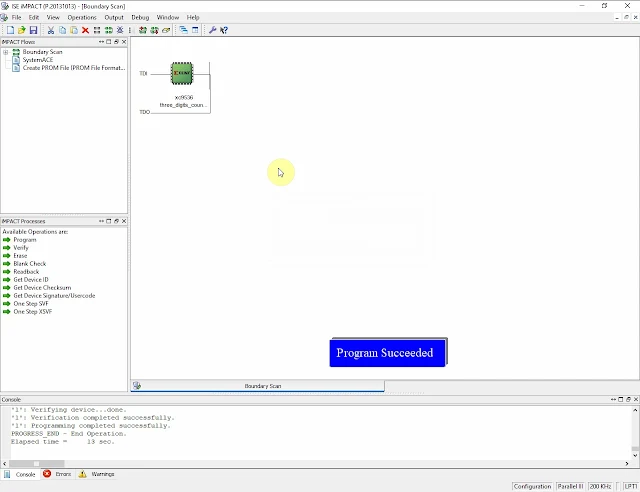
In this VHDL Example, an XC9536 CPLD will drive a three-digit common cathode multiplexing display. Each digits represent individual counting value ranges from 0 to 9 decimal values. A larger CPLD can create a 0 to 999 digital counters but this small XC9536 CPLD run out of resource. So I just design an individual digit counters.
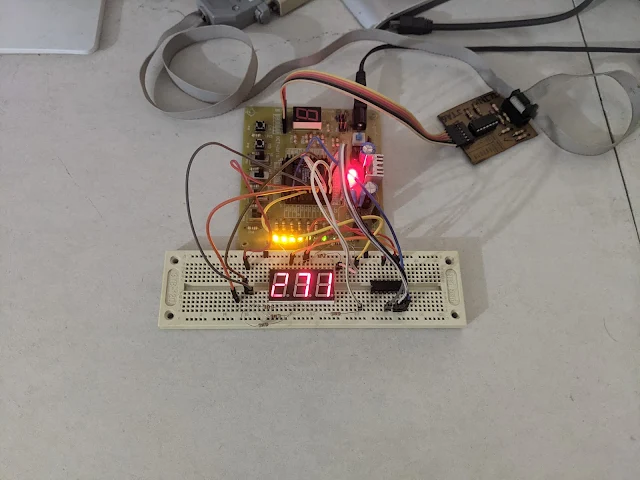
Running Circuit on an XC9536 CPLD Prototyping Board |
This digital circuit design contains only on sequential process activates by input clock and reset signal.
if ---------------------------------------------------------------------------------- -- Company: -- Engineer: -- -- Create Date: 09:36:40 12/12/2023 -- Design Name: -- Module Name: mux_counter - Behavioral -- Project Name: -- Target Devices: -- Tool versions: -- Description: -- -- Dependencies: -- -- Revision: -- Revision 0.01 - File Created -- Additional Comments: -- ---------------------------------------------------------------------------------- library IEEE; use IEEE.STD_LOGIC_1164.ALL; -- Uncomment the following library declaration if using -- arithmetic functions with Signed or Unsigned values --use IEEE.NUMERIC_STD.ALL; -- Uncomment the following library declaration if instantiating -- any Xilinx primitives in this code. --library UNISIM; --use UNISIM.VComponents.all; entity mux_counter is Port ( CLK : in STD_LOGIC; RST : in STD_LOGIC; UP_001 : in STD_LOGIC; UP_010 : in STD_LOGIC; UP_100 : in STD_LOGIC; COM : out STD_LOGIC_VECTOR (2 downto 0); DAT : out STD_LOGIC_VECTOR (7 downto 0)); end mux_counter; architecture Behavioral of mux_counter is type array_1 is array(0 to 9) of STD_LOGIC_VECTOR (7 downto 0); signal display : array_1 :=(x"3F",x"06",x"5B",x"4F",x"66",x"6D",x"7D",x"07",x"7F",x"6F"); begin process(CLK,RST,UP_001,UP_010,UP_100) variable freq_count : INTEGER RANGE 0 TO 2:=0; variable var_unit : INTEGER RANGE 0 TO 9:=0; variable var_ten : INTEGER RANGE 0 TO 9:=0; variable var_hun : INTEGER RANGE 0 TO 9:=0; begin if(RST='0') then var_unit:=0; var_ten:=0; freq_count:=0; elsif(CLK'EVENT AND CLK='1') then freq_count:=freq_count+1; CASE freq_count IS WHEN 0 => DAT<=display(var_unit); COM<="001"; WHEN 1 => DAT<=display(var_ten); COM<="010"; WHEN 2 => DAT<=display(var_hun); COM<="100"; if(UP_001='0') then var_unit:=var_unit+1; if(var_unit>9) then var_unit:=0; end if; end if; if(UP_010='0') then var_ten:=var_ten+1; if(var_ten>9) then var_ten:=0; end if; end if; if(UP_100='0') then var_hun:=var_hun+1; if(var_hun>9) then var_hun:=0; end if; end if; WHEN OTHERS => NULL; END CASE; end if; end process; end Behavioral;
Multiplexing display processed by the VHDL WHEN statement. Each input counting buttons are also place inside the WHEN statement because they require a longer period to be activated. So it reduce switch bouncing.
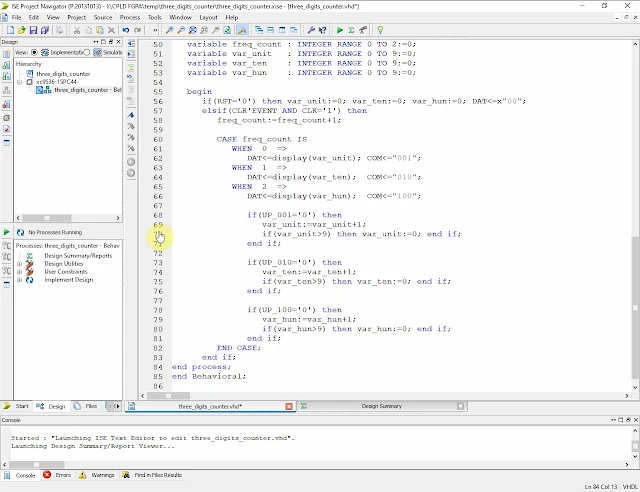
Source Code Windows |
I assigned its I/O pins as follow.
Xilinx PACE |
Click save and close this windows a user constraints file will automatically generated by software.
#PACE: Start of PACE I/O Pin Assignments
NET "CLK" LOC = "P5" ;
NET "COM<0>" LOC = "P42" ;
NET "COM<1>" LOC = "P43" ;
NET "COM<2>" LOC = "P44" ;
NET "DAT<0>" LOC = "P33" ;
NET "DAT<1>" LOC = "P34" ;
NET "DAT<2>" LOC = "P35" ;
NET "DAT<3>" LOC = "P36" ;
NET "DAT<4>" LOC = "P37" ;
NET "DAT<5>" LOC = "P38" ;
NET "DAT<6>" LOC = "P39" ;
NET "DAT<7>" LOC = "P40" ;
NET "RST" LOC = "P26" ;
NET "UP_001" LOC = "P18" ;
NET "UP_010" LOC = "P19" ;
NET "UP_100" LOC = "P25" ;
#PACE: Start of PACE Area Constraints
#PACE: Start of PACE Prohibit Constraints
#PACE: End of Constraints generated by PACE
An Xilinx Parallel Cable III still useable in Xilinx ISE Design Suites 14.7.
CPLD Reports |
Xilinx Parallel Cable III JTAG Programming for XC9536 CPLD |
If you are new to VHDL and Xilinx ISE Design Tool you can watch this video on YouTube.
Click here to download its source file.
No comments:
Post a Comment