In this VHDL example, I use a Xilinx XC9536 CPLD to create a digital up counter with a two-digit multiplexing seven-segment display. This counter will count up to 99 before it rolls down to 0. This CPLD has limited resource so we can not create more digits or temporary variable to process this circuit, even a three-digit digital up counter.
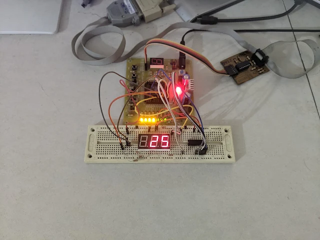
XC9536 CPLD Hardware Experiment |
In this design there are three inputs, clock, reset, and count push button. Clock signal is activated from low to high transition while reset and count signal are active low signals.
---------------------------------------------------------------------------------- -- Company: -- Engineer: -- -- Create Date: 19:32:59 12/12/2023 -- Design Name: -- Module Name: counter_mux - Behavioral -- Project Name: -- Target Devices: -- Tool versions: -- Description: -- -- Dependencies: -- -- Revision: -- Revision 0.01 - File Created -- Additional Comments: -- ---------------------------------------------------------------------------------- library IEEE; use IEEE.STD_LOGIC_1164.ALL; -- Uncomment the following library declaration if using -- arithmetic functions with Signed or Unsigned values --use IEEE.NUMERIC_STD.ALL; -- Uncomment the following library declaration if instantiating -- any Xilinx primitives in this code. --library UNISIM; --use UNISIM.VComponents.all; entity counter_mux is Port ( CLK : in STD_LOGIC; RST : in STD_LOGIC; CNT : in STD_LOGIC; COM : out STD_LOGIC_VECTOR (1 downto 0); DAT : out STD_LOGIC_VECTOR (7 downto 0)); end counter_mux; architecture Behavioral of counter_mux is type array_1 is array(0 to 9) of STD_LOGIC_VECTOR (7 downto 0); signal display : array_1 :=(x"3F",x"06",x"5B",x"4F",x"66",x"6D",x"7D",x"07",x"7F",x"6F"); begin process(CLK,RST) variable freq_count : INTEGER RANGE 0 TO 1:=0; variable press_count : INTEGER RANGE 0 TO 9:=0; variable press_10 : INTEGER RANGE 0 TO 9:=0; variable press_sw : INTEGER RANGE 0 TO 10:=0; begin if(RST='0') then press_count:=0; press_10:=0; DAT<=x"00"; elsif(CLK'EVENT AND CLK='1') then freq_count:=freq_count+1; -- 7-Segment Process CASE freq_count IS WHEN 0 => DAT<=display(press_count); COM<="01"; WHEN 1 => DAT<=display(press_10); COM<="10"; -- Push Button Process press_sw:=press_sw+1; if(CNT='0' AND press_sw>=7) then press_count:=press_count+1; press_sw:=0; if(press_count>9) then press_count:=0; press_10:=press_10+1; end if; if(press_10>9) then press_count:=0; press_10:=0; end if; end if; WHEN OTHERS => NULL; END CASE; end if; end process; end Behavioral;
After the design implementation this circuit consume a lot of the SX9536's resource. So we can not add more features into this design. I assigned its I/O pins using Xilinx PACE as follow.
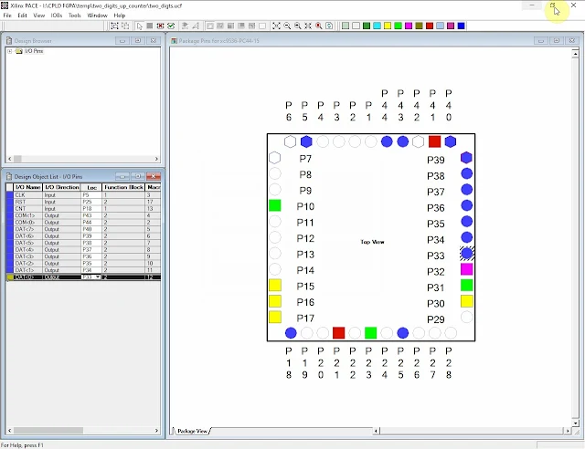
Xilinx PACE |
Its generated user constraint file listed below.
#PACE: Start of PACE I/O Pin Assignments
NET "CLK" LOC = "P5" ;
NET "CNT" LOC = "P18" ;
NET "COM<0>" LOC = "P44" ;
NET "COM<1>" LOC = "P43" ;
NET "DAT<0>" LOC = "P33" ;
NET "DAT<2>" LOC = "P35" ;
NET "DAT<3>" LOC = "P36" ;
NET "DAT<4>" LOC = "P37" ;
NET "DAT<5>" LOC = "P38" ;
NET "DAT<6>" LOC = "P39" ;
NET "DAT<7>" LOC = "P40" ;
NET "RST" LOC = "P25" ;
#PACE: Start of PACE Area Constraints
#PACE: Start of PACE Prohibit Constraints
#PACE: End of Constraints generated by PACE
Then we will need to run the Implement Design again to get its programming file.
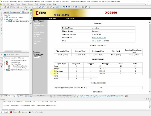
CPLD Reports |
After the Implement Design is finished we can see the reports.
I still use Parallel Cable III in iMPACT tool to program this device.
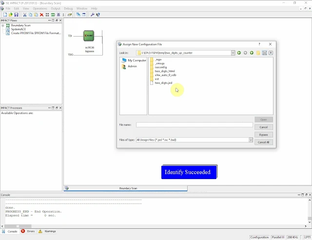
Xilinx iMPACT |
Click here to download its source file.
No comments:
Post a Comment