In this VHDL example, I design a Serial Peripheral Interface (SPI) receiver circuit that can drive a two-digit multiplexing display. The SPI receiver module is similar to a SN74HC164 serial-in-parallel-out shift registers. This module contains two shift registers inside. These two registers connects individually connect to two output port that drive to a two-digit multiplexing display.
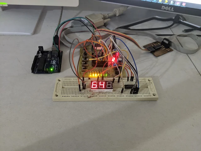
I an Arduino Uno to send a serial data package over the SPI to the XC9536 CPLD on board. |
SPI module does not need internal clock source. But the multiplexing display module needs a clock source to drive its output display at a rate of 16 milliseconds. I use an NE555 square wave oscillator to create a timing signal with a frequency of 60Hz for multiplexing display driving.
This design contains two process one's for SPI receiver module, and another one's for multiplexing display driving. These two processes are concurrent so the multiplexing display process does not need to wait or get interrupted by the SPI receiving process.
---------------------------------------------------------------------------------- -- Company: -- Engineer: -- -- Create Date: 08:34:17 12/15/2023 -- Design Name: -- Module Name: spi_display_2 - Behavioral -- Project Name: -- Target Devices: -- Tool versions: -- Description: -- -- Dependencies: -- -- Revision: -- Revision 0.01 - File Created -- Additional Comments: -- ---------------------------------------------------------------------------------- library IEEE; use IEEE.STD_LOGIC_1164.ALL; -- Uncomment the following library declaration if using -- arithmetic functions with Signed or Unsigned values --use IEEE.NUMERIC_STD.ALL; -- Uncomment the following library declaration if instantiating -- any Xilinx primitives in this code. --library UNISIM; --use UNISIM.VComponents.all; entity spi_display_2 is Port ( OSC : in STD_LOGIC; RST : in STD_LOGIC; TEST: in STD_LOGIC; SCLK : in STD_LOGIC; SDAT : in STD_LOGIC; COM : out STD_LOGIC_VECTOR (1 downto 0); LED : out STD_LOGIC_VECTOR (7 downto 0)); end spi_display_2; architecture Behavioral of spi_display_2 is signal reg_0,reg_1 : STD_LOGIC_VECTOR(7 DOWNTO 0):=x"00"; begin -- SPI Receiver Block spi_receive: process(SCLK,RST) begin if(RST='0') then reg_0<=x"00"; reg_1<=x"00"; elsif(SCLK'EVENT AND SCLK='1') then -- Serial Data Receive reg_0(0)<=SDAT; reg_0(1)<=reg_0(0); reg_0(2)<=reg_0(1); reg_0(3)<=reg_0(2); reg_0(4)<=reg_0(3); reg_0(5)<=reg_0(4); reg_0(6)<=reg_0(5); reg_0(7)<=reg_0(6); reg_1(0)<=reg_0(7); reg_1(1)<=reg_1(0); reg_1(2)<=reg_1(1); reg_1(3)<=reg_1(2); reg_1(4)<=reg_1(3); reg_1(5)<=reg_1(4); reg_1(6)<=reg_1(5); reg_1(7)<=reg_1(6); end if; end process spi_receive; -- Multiplexing Display Block display_multiplex: process(OSC,RST) variable ticks : INTEGER RANGE 0 TO 1:=0; begin if(RST='0') then ticks:=0; COM<="00"; LED<=x"00"; elsif(OSC'EVENT AND OSC='1') then ticks:=ticks+1; if(test='1') then CASE ticks IS WHEN 0 => LED<=reg_0; COM<="01"; WHEN 1 => LED<=reg_1; COM<="10"; WHEN OTHERS => NULL; END CASE; else CASE ticks IS WHEN 0 => LED<=x"3F"; COM<="01"; WHEN 1 => LED<=x"06"; COM<="10"; WHEN OTHERS => NULL; END CASE; end if; end if; end process display_multiplex; end Behavioral;
As we can see the display has three digits but I can use only two digits because the XC9536 CPLD has limited resource. I can not add one more shift registers signal.
I assign all of its I/O pins as follow.
Xilinx PACE |
Its user constraints file is automatically generated after the Xilinx PACE is saved.
#PACE: Start of PACE I/O Pin Assignments
NET "COM<0>" LOC = "P42" ;
NET "COM<1>" LOC = "P43" ;
NET "LED<0>" LOC = "P33" ;
NET "LED<1>" LOC = "P34" ;
NET "LED<2>" LOC = "P35" ;
NET "LED<3>" LOC = "P36" ;
NET "LED<4>" LOC = "P37" ;
NET "LED<5>" LOC = "P38" ;
NET "LED<6>" LOC = "P39" ;
NET "LED<7>" LOC = "P40" ;
NET "OSC" LOC = "P5" ;
NET "RST" LOC = "P25" ;
NET "SCLK" LOC = "P18" ;
NET "SDAT" LOC = "P19" ;
NET "TEST" LOC = "P26" ;
#PACE: Start of PACE Area Constraints
#PACE: Start of PACE Prohibit Constraints
#PACE: End of Constraints generated by PACE
I still use a Xilinx Parallel Cable III to program this CPLD.
Xilinx iMPACT Tools |
We don't need to press the SPI serial data and serial clock manually. We just use an Arduino Uno board to send SPI data to this board. The Arduino uses three pins, MOSI, SCK, and reset to connect to the CPLD.
The Arduino program below sends a counting variable ranging from 0 to 99 to the CPLD.
#include<SPI.h> void setup() { SPI.begin(); pinMode(10,OUTPUT); digitalWrite(10,LOW); delay(1); digitalWrite(10,HIGH); SPI.transfer(0x3F); SPI.transfer(0x3F); delay(2500); } int count=0; const char _7_SEG[10]={0x3F,0x06,0x5B,0x4F,0x66,0x6D,0x7D,0x07,0x7F,0x6F,}; void loop() { SPI.transfer(_7_SEG[count%10]); SPI.transfer(_7_SEG[count/10]); delay(250); count++; if(count>99) count=0; }
This program sends a random decimal number between 0 and 99 to the CPLD board.
#include<SPI.h> void setup() { SPI.begin(); pinMode(10,OUTPUT); digitalWrite(10,LOW); delay(1); digitalWrite(10,HIGH); SPI.transfer(0x3F); SPI.transfer(0x3F); delay(2500); } int myNumbers; const char _7_SEG[10]={0x3F,0x06,0x5B,0x4F,0x66,0x6D,0x7D,0x07,0x7F,0x6F,}; void loop() { myNumbers=random(99); SPI.transfer(_7_SEG[myNumbers%10]); SPI.transfer(_7_SEG[myNumbers/10]); delay(500); }
Click here to download its source file.
No comments:
Post a Comment