Character LCD interfacing is very popular among electronics hobbyists. Using a minimum 8-bit microcontroller with Assembly language programming is very common. This simple 8-bit HD44780 character LCD can be tested manually by applying digital logic inputs by switches without using any controller.
Some electronics practitioners use a digital circuit created by some digital logic chips to control this character LCD. Similarly a Programmable Logic Device (PLD) can replace that complex digital electronics circuit. We can use schematic design or even an easier VHDL or Verilog coding to design an LCD interface circuit that will run on any CPLD or FPGA.
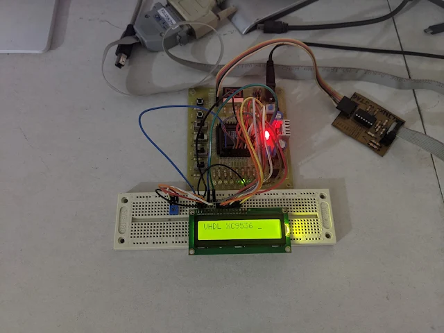
VHDL Code Testing on an experiment board |
In this VHDL example, I use an old simple Complex Programmable Logic Device (CPLD) to create a digital electronics circuit inside to interface with a HD44780 based character LCD module.
Using a Finite State Machine (FSM) model is very common this task. However I didn't follow all of this FSM model. I use a counter to activate each steps of data transfer between CPLD and LCD module.
An on-board 60Hz square wave oscillator is needed to active the circuit. LCD data and command are sequentially send to the LCD. It activated only at the high logic level of Enable (EN) output pin.
I use a low cost Chinese JHD162A LCD module. It costs around 2USD at local store.
JHD162A LCD Module Interfacing Pins |
The following VHDL codes will show a "VHDL XC9536" message on a character LCD. Then it will stop transferring data.
---------------------------------------------------------------------------------- -- Company: -- Engineer: -- -- Create Date: 16:57:52 12/16/2023 -- Design Name: -- Module Name: lcd_8 - Behavioral -- Project Name: -- Target Devices: -- Tool versions: -- Description: -- -- Dependencies: -- -- Revision: -- Revision 0.01 - File Created -- Additional Comments: -- ---------------------------------------------------------------------------------- library IEEE; use IEEE.STD_LOGIC_1164.ALL; -- Uncomment the following library declaration if using -- arithmetic functions with Signed or Unsigned values --use IEEE.NUMERIC_STD.ALL; -- Uncomment the following library declaration if instantiating -- any Xilinx primitives in this code. --library UNISIM; --use UNISIM.VComponents.all; entity lcd_8 is Port ( CLK : in STD_LOGIC; RST : in STD_LOGIC; RS : out STD_LOGIC; EN : out STD_LOGIC; DB : out STD_LOGIC_VECTOR (7 downto 0)); end lcd_8; architecture Behavioral of lcd_8 is signal E : STD_LOGIC:='0'; begin clock: process(CLK,RST) variable ticks: INTEGER RANGE 0 TO 32:=0; begin if(RST='0') then ticks:=0; E<='0'; elsif(CLK'EVENT AND CLK='1') then if(ticks<32) then ticks:=ticks+1; E<=E XOR '1'; EN<=E; end if; end if; end process clock; process(E) variable temp : INTEGER RANGE 0 TO 16; begin if(RST='0') then temp:=0; DB<=x"00"; elsif(E'EVENT AND E='1') then temp:=temp+1; CASE temp IS WHEN 0 => RS<='0'; DB<=x"38"; -- 5x7 Two Lines WHEN 1 => RS<='0'; DB<=x"0F"; -- LCD On Cursor Blink WHEN 2 => RS<='0'; DB<=x"01"; -- Clear Screen WHEN 3 => RS<='0'; DB<=x"06"; -- LCD Shift Cursor Right ---------------------------------- WHEN 4 => RS<='1'; DB<=x"56"; -- V WHEN 5 => RS<='1'; DB<=x"48"; -- H WHEN 6 => RS<='1'; DB<=x"44"; -- D WHEN 7 => RS<='1'; DB<=x"4C"; -- L WHEN 8 => RS<='1'; DB<=x"20"; -- SPACE WHEN 9 => RS<='1'; DB<=x"58"; -- X WHEN 10 => RS<='1'; DB<=x"43"; -- C WHEN 11 => RS<='1'; DB<=x"39"; -- 9 WHEN 12 => RS<='1'; DB<=x"35"; -- 5 WHEN 13 => RS<='1'; DB<=x"33"; -- 3 WHEN 14 => RS<='1'; DB<=x"36"; -- 6 WHEN 15 => RS<='1'; DB<=x"20"; -- SPACE WHEN 16 => RS<='1'; DB<=x"20"; -- SPACE WHEN OTHERS => NULL; END CASE; end if; end process; end Behavioral;
Don't forget to assign its I/O pins. The LCD 8-bit data bus shares with on-board LEDs.
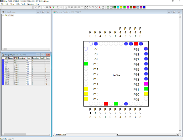
Xilinx PACE Tool - I/O Pin Assignments |
We will need to run the Implement Design again to wire its I/O pins. We will see its CPLD Reports.
CPLD Reports |
If you have a Desktop computer with a legacy parallel port we can use a Xilinx Parallel Cable III JTAG to program this CPLD. However a modern USB JTAG is currently widely used with an affordable price. A USB JTAG cable is very stable to use than a legacy one's.
Click here to download its VHDL, UCF, and JED files.
No comments:
Post a Comment