Friday, December 8, 2023

XC9536 CPLD LED Chasing Using VHDL

In this VHDL Example, I use ROL (Rotate Left) and ROR (Rotate Right) operators to chase the LEDs left or right. An input switch determines its chasing direction. A frequency divider is added to get a lower frequency driven from a NE555 square wave oscillator.

XC9536 CPLD Rotates LED Using VHDL
CPLD Hardware Test


VHDL source is quite simple due to the rotate operators.

  1. ----------------------------------------------------------------------------------
  2. -- Company:
  3. -- Engineer:
  4. --
  5. -- Create Date: 14:35:50 12/08/2023
  6. -- Design Name:
  7. -- Module Name: LED_ROTATE - Behavioral
  8. -- Project Name:
  9. -- Target Devices:
  10. -- Tool versions:
  11. -- Description:
  12. --
  13. -- Dependencies:
  14. --
  15. -- Revision:
  16. -- Revision 0.01 - File Created
  17. -- Additional Comments:
  18. --
  19. ----------------------------------------------------------------------------------
  20. library IEEE;
  21. use IEEE.STD_LOGIC_1164.ALL;
  22.  
  23. -- Uncomment the following library declaration if using
  24. -- arithmetic functions with Signed or Unsigned values
  25. --use IEEE.NUMERIC_STD.ALL;
  26.  
  27. -- Uncomment the following library declaration if instantiating
  28. -- any Xilinx primitives in this code.
  29. --library UNISIM;
  30. --use UNISIM.VComponents.all;
  31.  
  32. entity LED_ROTATE is
  33. Port ( CLK : in STD_LOGIC;
  34. SEL : in STD_LOGIC;
  35. LED : out BIT_VECTOR (7 downto 0));
  36. end LED_ROTATE;
  37.  
  38. architecture Behavioral of LED_ROTATE is
  39.  
  40. signal tmp : BIT_VECTOR(7 DOWNTO 0) :=X"01";
  41.  
  42. begin
  43.  
  44. process(CLK,SEL)
  45. variable count : INTEGER RANGE 0 TO 9;
  46. begin
  47. if(clk'event and clk = '1') then
  48. count:=count+1;
  49. if(count=9) then
  50. if(sel='0') then tmp<=tmp ROL 1;
  51. else tmp<=tmp ROR 1;
  52. end if;
  53. end if;
  54. LED<=tmp;
  55. end if;
  56. end process;
  57. end Behavioral;
  58.  
  59.  

I assign all the I/O pin as follow.

#PACE: Start of Constraints generated by PACE
#PACE: Start of PACE I/O Pin Assignments
NET "CLK"  LOC = "P5"  ; 
NET "LED<0>"  LOC = "P40"  ; 
NET "LED<1>"  LOC = "P39"  ; 
NET "LED<2>"  LOC = "P38"  ; 
NET "LED<3>"  LOC = "P37"  ; 
NET "LED<4>"  LOC = "P36"  ; 
NET "LED<5>"  LOC = "P35"  ; 
NET "LED<6>"  LOC = "P34"  ; 
NET "LED<7>"  LOC = "P33"  ; 
NET "SEL"  LOC = "P25"  ;
#PACE: Start of PACE Area Constraints
#PACE: Start of PACE Prohibit Constraints
#PACE: End of Constraints generated by PACE

Each I/O device are already placed on the XC9536 CPLD Test Board.

Its RTL schematic is shown below.
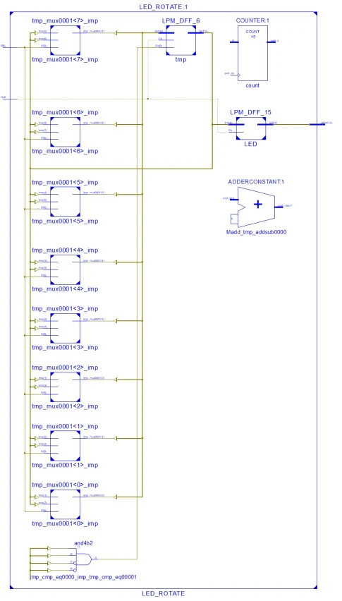
XC9536 CPLD Rotates LED Using VHDL
RTL

I use a Xilinx Parallel Cable III to program this CPLD.

XC9536 CPLD Rotates LED Using VHDL
iMPACT Device Programming Using Parallel Cable III

It still work on a Desktop PC operated by Microsoft Windows 10.


Click here to download its source file.

No comments:

Post a Comment

Labels

ADC (10) Analog (14) Arduino (12) Atmega16 (19) Audio (2) AVR (20) Charger (1) Cortex-M0 (1) Counter (10) CPLD (25) Digital I/O (22) Display (34) EEPROM (2) Environment Sensor (1) esp8266 (2) Experiment Board (10) I2C (4) Interrupt (7) LCD (1) LDmicro (29) measurement and instrumentation (7) Microchip Studio (3) MikroC (1) One-Shot (3) OpAmp (1) PCB (31) PIC16 Microcontrollers (16) PIC16F877A (2) PIC16F887 MikroC (22) PLC (35) PWM (11) Regulator (1) RTC (2) Sensor (8) Shift Registers (5) SPI (5) Timer (34) UART (2) ultra-sonic sensor (1) USB (1) VHDL (21) xc8 (1) XC95108 (9) XC9536 (15) XC9572 (1) Xilinx (23) Xilinx ISE (22)