A digital electronics ring counter chip is popular for electronics hobbyists especially in a DIY LED chasing circuit. A common digital IC ring counter is the CD4017. It's easily to find with a very low price.
 |
| Ring Counter Testing On XC9536 CPLD Board |
 |
| A Ring Counter Board Using CD4017 And NE555 Oscillator |
However we can use a programmable logic device to design a simple ring counter circuit. A small CPLD "XC9536" can do this job. I use VHDL to build a ring counter. We can customize a number of outputs and its operating modes.
I use clock and clear input signal. The output is an 8-bit standard logic vector. Input clock is driven from a 60Hz on-board NE555 square signal generator.
Using VHDL to design this circuit is very easy. If we don't prefer it we can design this ring counter digital circuit using schematic tool.
 |
| Register Transfer Level - RTL |
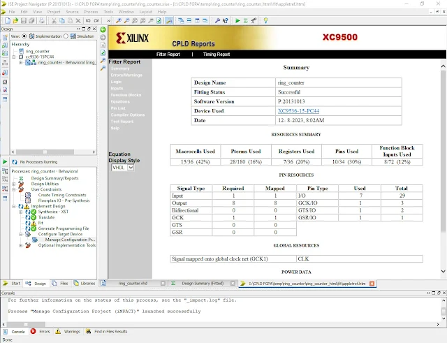
We can look at its CPLD reports to know its resource usage.
 |
| CPLD Reports |
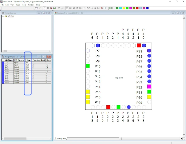
After the design is succeed we need to assign its I/O pins using Floorplan IO.
 |
| Xilinx PACE |
When we already assigned all I/O pins we need to save and close it. A user constraint ".ucf" will be generated by software.
#PACE: Start of PACE I/O Pin Assignments
NET "CLK" LOC = "P5" ;
NET "CLR" LOC = "P25" ;
NET "Q<0>" LOC = "P40" ;
NET "Q<1>" LOC = "P39" ;
NET "Q<2>" LOC = "P38" ;
NET "Q<3>" LOC = "P37" ;
NET "Q<4>" LOC = "P36" ;
NET "Q<5>" LOC = "P35" ;
NET "Q<6>" LOC = "P34" ;
NET "Q<7>" LOC = "P33" ;
#PACE: Start of PACE Area Constraints
#PACE: Start of PACE Prohibit Constraints
#PACE: End of Constraints generated by PACE
We will need to re-run the Implement Design again to get CPLD ".jed" program file. We have to run the iMPACT tool to program the target CPLD device.
 |
| iMPACT |
I use a parallel port JTAG cable "Parallel Cable III". The version of ISE Design is 14.7. It run on Windows 10 64-bit. Some of IBM type Desktop PC have a legacy parallel port. Click here to download the VHDL and user constraint file.
No comments:
Post a Comment