Sunday, December 10, 2023

XC9536 CPLD 7-Segment Up Down Counter Using VHDL

Overview

In this VHDL tutorial, I will design an up/down counter using VHDL code. Alternatively, we can use an ASIC 4516 and a 4511 chip to create this type of digital counter. However using a CPLD we can create and customize any digital circuit or ASIC by VHDL, Verilog code, or even schematic design tool.


XC9536 CPLD 7-Segment Up Down Counter Using VHDL
XC9536 CPLD Prototyping Board
I use my own XC9536 CPLD prototyping board to create this circuit design. It requires a little VHDL code, and half its macro-cells. Additionally, we can map its I/O device to any CPLD I/O pins.

VHDL Code

Its source code is very simple to write, I use one sequential block (process). The IF statement to make a frequency division, and to test digital logic input's state change. Additionally, the CASE Statement is used for decoding the output seven segments data. I added one active low reset signal to zero all variables.

  1. ----------------------------------------------------------------------------------
  2. -- Company:
  3. -- Engineer:
  4. --
  5. -- Create Date: 19:04:41 12/10/2023
  6. -- Design Name:
  7. -- Module Name: counter_ud - Behavioral
  8. -- Project Name:
  9. -- Target Devices:
  10. -- Tool versions:
  11. -- Description:
  12. --
  13. -- Dependencies:
  14. --
  15. -- Revision:
  16. -- Revision 0.01 - File Created
  17. -- Additional Comments:
  18. --
  19. ----------------------------------------------------------------------------------
  20. library IEEE;
  21. use IEEE.STD_LOGIC_1164.ALL;
  22.  
  23. -- Uncomment the following library declaration if using
  24. -- arithmetic functions with Signed or Unsigned values
  25. --use IEEE.NUMERIC_STD.ALL;
  26.  
  27. -- Uncomment the following library declaration if instantiating
  28. -- any Xilinx primitives in this code.
  29. --library UNISIM;
  30. --use UNISIM.VComponents.all;
  31.  
  32. entity counter_ud is
  33. Port ( RST : in STD_LOGIC;
  34. CLK : in STD_LOGIC;
  35. UP : in STD_LOGIC;
  36. DOWN : in STD_LOGIC;
  37. SSD : out STD_LOGIC_VECTOR (7 downto 0));
  38. end counter_ud;
  39.  
  40. architecture Behavioral of counter_ud is
  41.  
  42. begin
  43.  
  44. process(CLK, RST)
  45. variable freq_count : INTEGER RANGE 0 TO 29;
  46. variable press_count : INTEGER RANGE 0 TO 15;
  47.  
  48. begin
  49. if(RST = '0') then freq_count:=0; press_count:=0;
  50. elsif(CLK'event AND clk='1') then
  51. freq_count:=freq_count+1;
  52. if(freq_count>20) then
  53. if(UP='0') then
  54. press_count:=press_count+1; freq_count:=0;
  55. end if;
  56. if(DOWN='0') then
  57. press_count:=press_count-1; freq_count:=0;
  58. end if;
  59. end if;
  60. end if;
  61. -- 7-Segment Display Process
  62. CASE press_count IS
  63. WHEN 0 => SSD<=x"3F";
  64. WHEN 1 => SSD<=x"06";
  65. WHEN 2 => SSD<=x"5B";
  66. WHEN 3 => SSD<=x"4F";
  67. WHEN 4 => SSD<=x"66";
  68. WHEN 5 => SSD<=x"6D";
  69. WHEN 6 => SSD<=x"7D";
  70. WHEN 7 => SSD<=x"07";
  71. WHEN 8 => SSD<=x"7F";
  72. WHEN 9 => SSD<=x"6F";
  73. WHEN 10 => SSD<=x"77";
  74. WHEN 11 => SSD<=x"7C";
  75. WHEN 12 => SSD<=x"39";
  76. WHEN 13 => SSD<=x"5E";
  77. WHEN 14 => SSD<=x"79";
  78. WHEN 15 => SSD<=x"71";
  79. WHEN OTHERS => NULL;
  80. END CASE;
  81. end process;
  82.  
  83. end Behavioral;
  84.  
  85.  

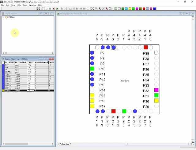
Up and Down logic input are active low. They are connected to pin 18 and 19 respectively. They are activated by pressing the buttons.

I/O Pin Assignments

I assign its I/O pins by using Xilinx PACE tool as follow.
XC9536 CPLD 7-Segment Up Down Counter Using VHDL
Pin Assignments

A user constraints *.ucf file will be generated after we save the PACE.

#PACE: Start of Constraints generated by PACE
#PACE: Start of PACE I/O Pin Assignments
NET "CLK"  LOC = "P5"  ;
NET "DOWN"  LOC = "P19"  ;
NET "RST"  LOC = "P25"  ;
NET "SSD<0>"  LOC = "P3"  ;
NET "SSD<1>"  LOC = "P4"  ;
NET "SSD<2>"  LOC = "P8"  ;
NET "SSD<3>"  LOC = "P9"  ;
NET "SSD<4>"  LOC = "P11"  ;
NET "SSD<5>"  LOC = "P13"  ;
NET "SSD<6>"  LOC = "P12"  ;
NET "SSD<7>"  LOC = "P7"  ;
NET "UP"  LOC = "P18"  ;
#PACE: Start of PACE Area Constraints
#PACE: Start of PACE Prohibit Constraints
#PACE: End of Constraints generated by PACE

We can also create this source file and write the codes manually. After this step is completed, we will need to re-run the Implement Design to obtain its programming file *.jed .

Device Programming

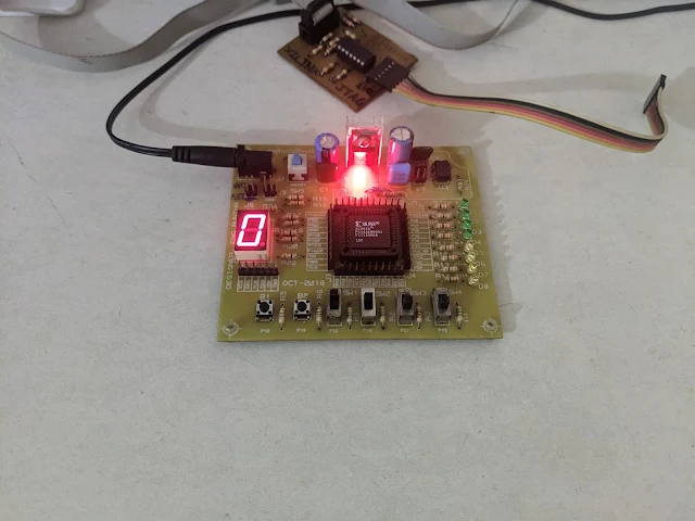
We just run the iMPACT tool to program the target XC9536 CPLD. A high speed USB JTAG is popular now. However I still use a legacy parallel port JTAG header. It still present in Xilinx ISE Design Suite 14.7, and Microsoft Windows 10. My HP MT-6300 Desktop PC has a legacy PCI Express parallel port (LPT-25) card.

XC9536 CPLD 7-Segment Up Down Counter Using VHDL
iMPACT Tool

Its operating speed is suitable for a small programming file. 
XC9536 CPLD 7-Segment Up Down Counter Using VHDL
Program Succeeded  


Click here to download its source file.


No comments:

Post a Comment

Labels

ADC (10) Analog (14) Arduino (12) Atmega16 (19) Audio (2) AVR (20) Charger (1) Cortex-M0 (1) Counter (10) CPLD (25) Digital I/O (22) Display (34) EEPROM (2) Environment Sensor (1) esp8266 (2) Experiment Board (10) I2C (4) Interrupt (7) LCD (1) LDmicro (29) measurement and instrumentation (7) Microchip Studio (3) MikroC (1) One-Shot (3) OpAmp (1) PCB (31) PIC16 Microcontrollers (16) PIC16F877A (2) PIC16F887 MikroC (22) PLC (35) PWM (11) Regulator (1) RTC (2) Sensor (8) Shift Registers (5) SPI (5) Timer (34) UART (2) ultra-sonic sensor (1) USB (1) VHDL (21) xc8 (1) XC95108 (9) XC9536 (15) XC9572 (1) Xilinx (23) Xilinx ISE (22)