Introduction
In previous post we demonstrate how to program for fast PWM waveform creates by Timer/Counter0 peripheral module. Beside of fast PWM waveform generation, Timer/Counter0 offers another more precise PWM mode – phase correct PWM.
Phase Correct PWM Mode
As mentioned in previous post, fast PWM mode waveform has only 8-bit counting register. However a phase correct PWM offer a higher resolution as twice compares to fast PWM mode. This mode is preferred for a precise motor control application.
Operation Of Phase Correct PWM
A high resolution of waveform generation of this mode make by a two-direction countering of Timer/Counter0 register (TCNT0).
 |
| Timing diagram of phase correct PWM mode from device’s datasheet |
Waveform generation of this PWM mode has two polarities – non-inverting
and inverting output at OC0 pin. A non-inverting waveform generation
occurs when up counting (BOTTOM to MAX) that TCNT0 compares with OCR0,
and clear OC0 flag at compare match . OC0 flag is set when down counting
(MAX to BOTTOM), and it’s clear at compare match.
An inverting phase correct PWM waveform generation its operation is inverse. These two type of waveform creation selected in Timer Control Register (TCCR0).
We can find its output frequency as follow,
 |
| Phase correct PWM output frequency’s equation |
Interfacing And Programming
It’s similar to fast PWM mode programming in previous post. However it’s different in register setting and its output frequency. I keep the hardware schematic and connection the same to the previous one’s.
Hardware Interfacing
There’s no change in hardware connection for this tutorial, as it’s already worked in previous tutorial for fast PWM mode.
 |
| Circuit Diagram |
ATMega16 supplies at +5V, clocks at 16MHz DC. The odd one’s is its output frequency at OC0/PB3 pin of Port B.
Registers Setting
There are some bits setting in Timer/Counter Control Register (TCCR0).
 |
| Timer/Counter0 Control Register (TCCR0) |
In the Waveform Generation Mode Bit, the software must set the WGM00 to force Timer/Counter0 works in phase correct PWM mode.
 |
| Waveform Generation Mode Bit |
Output Compare Register (OCR0) is also limit duty cycle of PWM waveform in this mode. Beside crystal oscillator frequency of microcontroller, Clock Select Bit define the PWM output frequency.
 |
| Clock Select Bit of Timer/Counter0 Control Register (TCCR0) |
Polarity of waveform for this PWM mode is selected in Compare Output Mode bit.
 |
| Compare Output Mode for Phase Correct PWM |
In this tutorial I preferred a non-inverting phase correct PWM mode. Thus COM01 must be putted to ‘1’.
AVR GCC Programming for Phase Correct PWM
In this tutorial, the microcontroller generate a PWM waveform with a frequency of 122.54Hz. Since microcontroller clock is 16MHz, I set Clock Select Bit to 1:256. Phase correct PWM output frequency is calculated by,
 |
| Calculation for frequency in phase correct PWM mode |
To get a 1:256 clock prescaler, the software must set CS02=1. AVR GCC of this minor example is written in Atmel Studio 7 IDE.
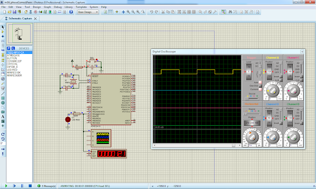
We can see the result in Proteus simulator below.
 |
| Simulation result in Proteus simulator |
The output frequency is 122Hz. However we can create a lower frequency using this PWM mode. Click here to download zip file of this working tutorial.
Adjusting Its Duty Cycle
Since Output Compare Register (OCR0) is changeable during run-time, the user can modify its duty cycle of phase correct PWM waveform using this register.
Adding Two Adjusting Buttons
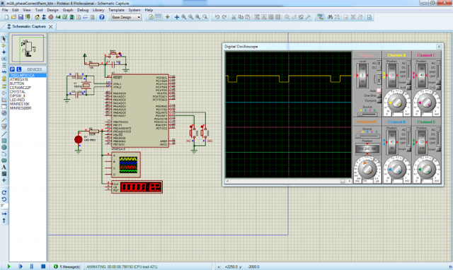
We use two user’s input push button to increase and decrease duty cycle of phase correct PWM waveform. These two buttons change the duty cycle of PWM waveform with a rate of 15.
A button connects to PD2 decrease duty cycle while another one’s connects to PD3 increase its duty cycle.
 |
| Proteus simulation of adjusting duty cycle of phase correct PWM mode |
Its frequency remains 122Hz. It excepts its variable duty cycle of waveform.
AVR GCC Source Code
There are some additional lines of code to handle input button events. Main program loop keeps track of input changes of these two buttons, connect to PD2 and PD3.
There’s no need to test this program on AVR development board due to duplication, as a similar work was already done in previous article. Click here to download zip file of this working example.

No comments:
Post a Comment