Introduction
Compare Output Mode of Timer/Counter0 is also calls waveform generation. It’s different from normal mode, CTC, and PWM mode.
We can use this mode to create a waveform in a form of toggling , set, and clear OC0 pin on compare match. However it’s just like a normal timer mode but it’s additionally able to trigger an output at OC0 pin. Toggling OC0 at compare match is just a square wave output with a programmable frequency.
Programming
Waveform generation mode is selected by Compare Output Mode bit for non-PWM mode of the Timer/Counter Control Register (TCCR0).
 |
| Compare Output Mode bit of TCCR0 |
Within this example I program the ATMega16 to toggle OC0 on compare match. Crystal frequency of microcontroller is 16MHz with its clock select bit of 1:1024. Hence the toggling output occurs for every,
 |
| Equation to find the toggling time of waveform generation |
We can find the frequency of square wave output as,
 |
| Equation to find waveform generation frequency |
Finally the microcontroller program coded to toggle OC0 output with a frequency of 30.52Hz.
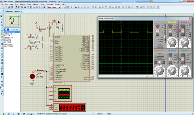
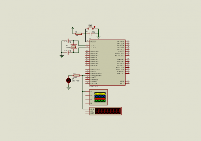
Let see the hardware simulation in Proteus.
 |
| Proteus simulation for waveform generation |
Click here to download zip file for this working example.

No comments:
Post a Comment