Introduction
ATMega16 Waveform Generation
As it’s already described in an earlier post, Timer/Counter0 could be configured to work in many ways such as one’s in fast PWM mode. The microcontroller controller can create a PWM waveform by a few register setting in source code.
What’s Pulse Width Modulation
Pulse Width Modulation (PWM) is technique that create an variable analog output voltage from an electronic device. Conventionally, digital electronic device output only digital signal.
 |
| A simple PWM waveform with various duty cycle |
Duty cycle defines the average analog output voltage of a PWM signal. Higher duty cycle generates more higher analog output voltage. As an instance, a 50% duty cycle of a +5V amplitude PWM waveform create an approximate 2.5V analog output voltage.
PWM is useful in controlling the speed of electric motor, adjusting the brightness of a lighting lamp, etc.
Timer/Counter0 In Fast PWM Mode
ATMega16 Timer/Counter0 Advantages
For an AVR ATMega16 microcontroller, the user can create an output waveform in various way but using a different number of coding. Timer/Counter0 offers two kind of PWM output – fast PWM and phase correction PWM mode. Each mode is easily selected using a few register setting in C code. Here we mention only fast PWM mode.
Some Required Registers
With various registers relate to Timer/Counter0 peripheral, fast PWM require only two of them – Timer/Counter Control Register (TCCR0) and Output Compare Register (OCR0).
Timer/Counter Control Register (TCCR0)
Selecting the Waveform Generation Mode Bits of this register forces Timer/Counter0 peripheral to work in various way.
 |
| Timer/Counter Control Register (TCCR0) |
Within this register the software setting set the WGM01=1 and WGM00=1 to configure this peripheral to work in fast PWM mode.
 |
| Waveform Generation Mode Bits |
Prescaler selection bit and microcontroller clock frequency define the output frequency of fast PWM. Its frequency could be calculated as,
 |
| Timer/Counter0 fast PWM frequency calculation |
Output Compare Register (OCR0)
This register defines the duty cycle of fast PWM waveform. It’s fixed or could be adjust by software during run-time. Timer/Counter0 register (TCNT0) regularly compare its incremental content with this register. On the match, the Output Compare (OC0) register is set or cleared, toggle an output waveform.
 |
| Timer/Counter0 Output Compare Register (OCR)) |
Fast PWM Operation
As the program runs, Timer/Counter0 register continuously compare its TCNT0 register with OCR0 register. Both registers are 8-bit wide. During the program execution, OCR0 could be modified to change the duty cycle of PWM.
 |
| Timing diagram of fast PWM mode |
Value of Output Compare (OC0) bit is update (set or clear) at the BOTTOM of TCNT0. Setting the OC0 at the BUTTOM generates a non-inverting mode fast PWM waveform. Clearing the OC0 at the BUTTOM generates an inverting mode fast PWM waveform.
These two mode of fast PWM waveform is selected using the Compare Output bit for fast PWM mode in TCCR0 register.
 |
| Fast PWM mode – Output Compare Mode |
Typically the program select a non-inverting mode for a single PWM waveform generation.
ATMega16 Fast PWM Programming
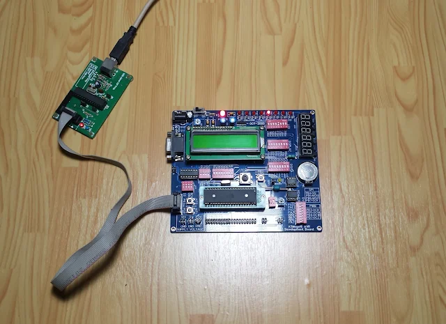
Here I use Atmel Studio 7 IDE to code the AVR GCC. Proteus simulator is a first programming testing in host PC. It offers a safe way and fast to prototype an electronic hardware virtually. Finally the embedded program will be test on an AVR ATMega16 development board.
Schematic Diagram Preparation
Using Proteus this hardware prototyping could be done for less than 10 minutes. The ATMega16 has a default supply voltage of +5V with a crystal oscillator of 16MHz frequency. It’s manually reset using its reset circuit via a push button.
 |
| Schematic diagram drawn using Proteus |
Without using this software the user can manually prototype this circuit on a single breadboard.
AVR GCC Program Preparation
With AVR GCC, programming the fast PWM requires a few lines of code. In this introductory example, Timer/Counter0 create a fast PWM waveform of 61Hz from its 16MHz crystal oscillator, with a 50% duty cycle.
In TCCR0 register, I select non-inverting fast PWM mode, with 1:1024 prescaler. We can calculate for its frequency as,
 |
| Calculation for fast PWM frequency |
To get a 50% frequency, OCR0 register must be set to 127 in decimal.
Finally, we can code the ATMega16 in AVR GCC as below.
Without physically circuit prototyping we can see this work in simulator.
 |
| Fast PWM simulation in Proteus |
Pin PB3 is a PWM output pin (OC0). It connects to an LED via a 680Ohm current limiting resistor its output is 50% less than usual.
Click here to download zip file of this working example. I tested this program on my AVR ATmega16 development board.
 |
| Fast PWM output at OC0/PB3 pin |
PB3/OC0 pin shows more flickering on its output LED due to low PWM frequency of 61Hz.
Adjusting duty cycle via buttons
We can add more input buttons to change the value of OCR0, thus adjusting its duty cycle. In this additional programming example, a button connects to PD2 lower the duty cycle while another button connects to PD3 raises its duty cycle.
 |
| Schematic diagram |
AVR GCC program of this example has some additional lines of code that read digital inputs, and change the duty cycle. The change of duty cycle has a rate of 25. It frequency is different from the previous one’s, in which,
 |
| Equation to find a nearby 1kHz fast PWM frequency. |
The result of frequency calculation is approximate to 1kHz.
Click here to download this working example in zip file. Without laboratory equipment such as oscilloscope, workbench power supply, etc. This program could be tested in simulator.
 |
| Simulation in Proteus |
Frequency of PWM in this simulator is 977Hz, approach to one’s in calculation.

No comments:
Post a Comment