Introduction
A timer of a microcontroller usually utilized to create a precise timing delay, a square wave output, a reference time to measure any received external pulse, etc. For instance, decoding the remote control signal requires a precise internal timer of a microcontroller to measure the time of true and false logic.
 |
| Simulation of Timer 0 |
As a microcontroller inside’s, a timer formed by one or two timer registers depend on the architectural design. For example, an 8-bit microcontroller with a 8-bit timer has an 8-bit timer register. A 16-bit timer of an 8-bit microcontroller composes of two 8-bit timer registers. Timer register automatically increase its content as the programmer properly configured it. It’s a read/write register. There are some essential registers relate to timer operation, a register to configure the incremental rate, a register to configure and check timer interrupt event.
Timer 0 Of ATMega16
ATmega16 microcontroller comes with a number of timers. Here we will briefly discuss about timer0 and its utilization. Literately, it’s referred as Timer/Counter0 as it could operate in timer or counter mode. For a simple explanation we only list it in timer mode.
A Brief Of Timer/Counter0
Timer/Counter0 is 8-bit timer or counter register. It can generate a PWM output to external analog device via pin OC0 as the programmer configured in codes.
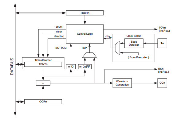
A block diagram lists below take from vendor device specification. It’s a general diagram of the 8-bit Timer/Counter of its ATMegaR microcontroller series.
 |
| Block diagram of 8-bit Timer/Counter0 of ATMega16 Microcontroller |
From this block diagram, the external pin OCn creates a PWM output signal. As the case of Timer/Counter0 it’s named as OC0. Tn is an external input for counter mode. Here it’s name as T0, an external pulse that fed to Timer/Counter0 whenever this module works as counter mode.
Relevant Registers
In Special Function Registers (SFR) space there are a number of registers. Those are storage register, control registers and interrupt flag register.
For a instance we will show only some fundamental registers that configure Timer/Counter0 to work in timer mode.
Timer/Counter Register – TCNT0
The program could directly read and write to this 8-bit register while the program is running.
 |
| Timer/Counter Register – TCNT0 |
In PWM mode modifying this register could make some problems.
Timer/Counter Control Register – TCCR0
This register largely control the operation of Pulse Width Modulation (PWM) generated by Timer/Counter0. It contains some bits that set the prescaler of PWM, counter and also timer.
 |
| Atmega16 TCCR0 register |
There are a lot of details for each bit in this register. Some bits in this register relate to timer mode. By default the module work in timer mode but with no clock source which means that the timer doesn’t increase its content.
The Compare Output Mode COM01:00 determine the operation of this module. The table lists below set the configuration of a non-PWM mode operation.
 |
| The Compare Output Mode COM01:00 |
As list above COM01:00 equal to “00” which keep this module in timer mode.
Clock Select Bits CS02:0 determine clock source, prescaler and transition for this module. The transition work only in counter mode.
 |
| TCCR0 clock selection bits of Timer/Counter0 in ATMega16 |
Timer/Counter Interrupt Flag Register – TIFR
Whenever the comparison of Timer/Counter match the the value of OCR0 register the Output Compare Flag 0 – OCF0 is set. However we will not talk about this here because the article is only about timer mode.
 |
| Timer/Counter Interrupt Flag Register – TIFR |
The Timer/Counter0 Overflow Flag (TOV0) is set whenever the timer register exceeds 0xFF (255 in decimal) and rolls back to 0. Whenever it happens the program set this bit to clear the interrupt flag.
Timer 0 Programming In Atmel Studio 7
Introduction
Using AVR GCC the programming for timer 0 is very short in code, and more understandable. Registers name are just like the labels listed in its device’s datasheet.
Now let program timer 0 of the ATMega16 from scratch. A simple introductory program show how to configure timer 0 in AVR GCC in Atmel Studio 7.
Module Preparation
Timer 0 clock source pulses by the microcontroller crystal clock as it’s pre-soldered on the AVR development board. The crystal oscillator frequency is 16 MHz. It’s clock period is,
1/(16000000 Hz) = 62.5 ns.
With its select-able prescaler I scale this clock source to 1024 time. So clock selection bits of the TCCR0 register must be, CS02=0 and CS00=0.
As a result timer 0 (TCNT0 register) increase its content for every,
1024 x 62.5 ns = 64 us.
This 8-bit register overflows when its content reaches 0xFF, setting the interrupt flag TOV0 in the TIFR register. The duration that the TOV0 flag is set is,
256 x 64 us = 16.3 ms.
Unlike other microcontroller such as PICMicro, to clear the interrupt flag the software must set that interrupt flag. That could be weird to most novice AVR programmer.
AVR Coding
As demonstrated above this embedded programming example toggles an output pin of port B for every 16.3 ms. It’s just like a square wave with a period of,
2 x 16.3 ms = 32.6 ms.
AVR GCC source code lists below.
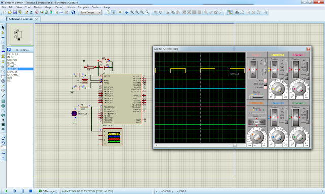
It’s schematic is drawn and simulated in Proteus because I don’t have a oscilloscope to test the physical hardware at the moment.
 |
| Schematic Diagram – The ATMega16 clocks from a 16 MHz crystal oscillator. |
The output wave form creates by timer 0 interrupt shown on a virtual oscilloscope as it’s simulated in Proteus.
 |
| The output wave form on PB0 of Port B. |
The clock period is 32.75 ms in software simulator. Click here to download zip file of this programming example.
Creating A One Second Delay
As mentioned earlier, the interrupt occurs for every 16.3 ms. The programmer can create more timing delay from this advantage using more optional C variables. For instance we want to create a one second delay. To make this work the programmer create a C variable that its content increase one by one for every 16.3 ms. We can the find the total count in one second by,
oneSecond = 1/0.0163 = 61 counts
AVR GCC program is 90% similar to the program written above but with some additional line of code that create a one second delay.
The schematic diagram is no other than the one’s shown above. Click here to download the zip file.
No comments:
Post a Comment