Introduction
Another feature of ATMega16 AVR microcontroller Timer/Counter0 peripheral is its Clear Timer on Compare Match (CTC) Mode. In this case the controller can only generate a square wave output on its OC0 output pin.
Its free running Timer/Counter0 Register (TCNT0) starts count until it reaches the value of the Output Compare Register (OCR0). At comparison matching the TOP, the TOV0 flag is set. Output logic change at OC0 pin is selected using software – set, clear, toggle, and disconnect.
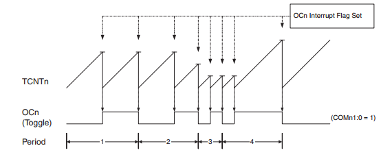 |
| Timing Diagram for CTC mode of Timer/Counter0 |
Assigning WGM01 of Waveform Generation Mode Bit of TCCR0 register to 1, put Timer/Counter0 to operate in Clear Timer on Compare Match (CTC) mode.
To generate square wave output at OC0, the software must set the Output Compare Mode bit in non-PWM mode to toggle OC0 pin at compare match.
 |
| Output Compare Mode bit in non-PWM mode |
Output Compare Register (OCR0) is a reference value for TCNT0. It’s changeable during run-time to change the output square wave’s frequency. Device’s datasheet states the formula of finding the frequency of square wave output as below,
 |
| N is prescaler factor 1, 8, 64, 256, or 1024 |
When the OCR0 register is set to 0 the maximum frequency of output waveform is haft of microcontroller clock.
ATMega16 Coding Using AVR GCC
Embedded controller’s program generates an output waveform at OC0 pin as square wave with a determined frequency. Software setting puts Timer/Counter0 module of this AVR device to work in CTC mode as we have described above.
We select CTC mode with its clock prescaler of 256, and OCR0 = 50. Then the output frequency of waveform at OC0 pin is,
 |
| Calculation for output frequency |
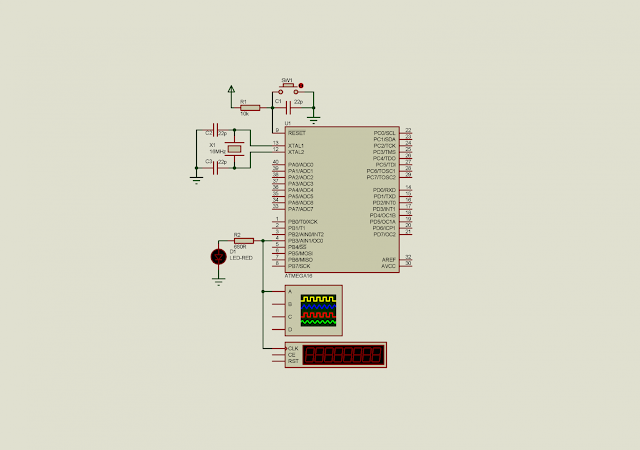
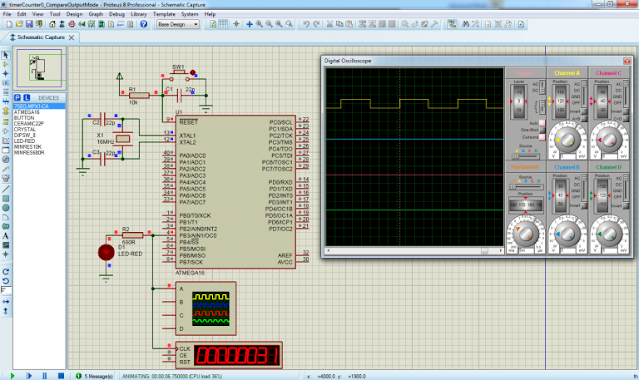
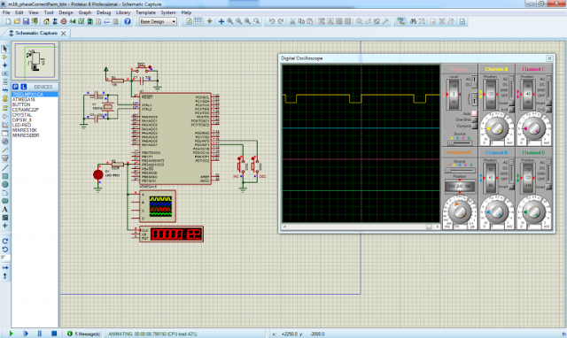
Without sophisticated laboratory equipment – oscilloscope, I test this microcontroller program in Proteus simulator.
 |
| Simulation in Proteus – The output frequency is 613Hz in software |
AVR GCC coding is done in Atmel Studio 7 as a preferred IDE.
Click here to download zip file of this AVR tutorial.
A Program to Create a 50Hz Frequency
Since Output Compare Register (OCR0) used for adjusting the frequency of output waveform in this mode, we can find its actual value to create a preferred frequency.
To get a lower 50Hz frequency we need to scale timer input to 1:1024 ( N=1024). With an equation stated by device’s manufacturer, we can find the value of OCR0 as follow,
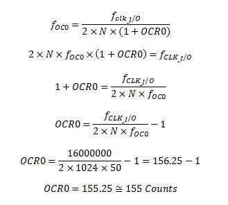 |
| Equation to find a 50Hz frequency |
So in software embedded C we must set CS02=1 and CS00=1, and OCR0=155.
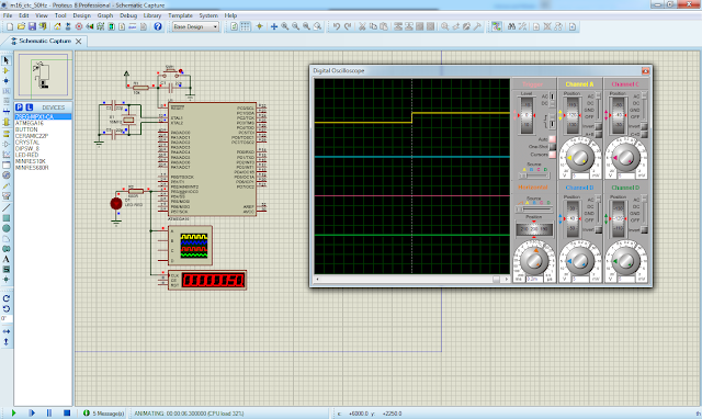
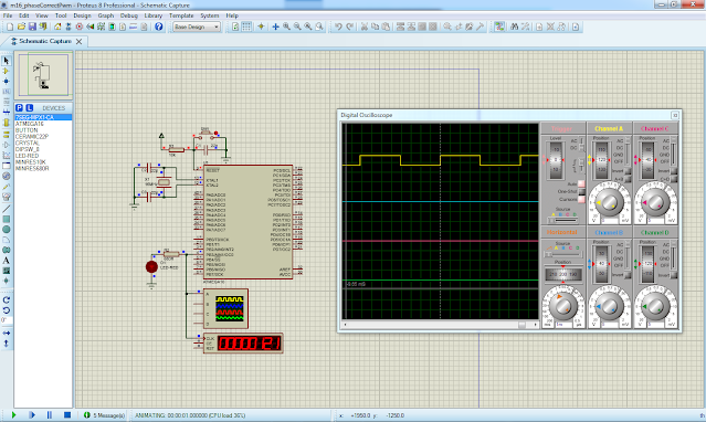
This embedded program is simulated in Proteus simulator.
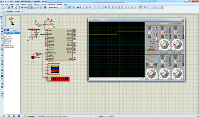 |
| Simulation result in Proteus |
