Introduction LM35
LM35 is thermometer that converter surrounding temperature to analog voltage. Its analog voltage voltage is proportional to temperature that is 10mV per degree Celsius. It's supplied from a DC voltage source ranging from 4 to 30V. Conversion temperature is between -55 to 150 degree Celsius.
Sample of this example program |
Dual-In-Line Package of TO-92 is very popular for hobbyist prototyping of this kind of sensor. It's a three-pin transistor-like electronics device. These three pins are VDD, VOUT, and GND.
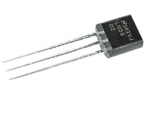
LM35DZ TO-92 transistor-like package |
From electronics component store this device costs below one USD.
Interfacing and Programming using MikroC
Using ADC module inside PIC16F887, temperature reading could be done easily and precise due to 10-bit resolution inside ADC module. Floating point calculation in program C allow result acquisition calculated within a line of C code.
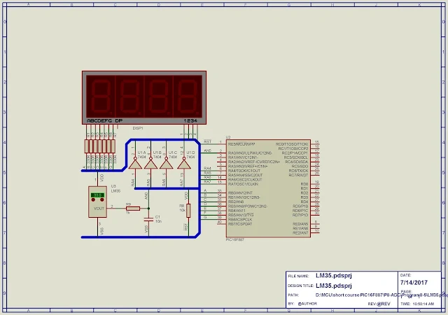
Circuit Diagram |
Temperature data will show on multiplexed display driven by PortB. Device supplied from stabilized 5V DC voltage with 8MHz internal oscillator.
MikroC source code:
#define STEP_SIZE 0.0048 #define ONE_SECOND 30 #define Volt_Per_Celcius 0.01 #define RATE 1 #define DIGIT1 PORTA.RA4 #define DIGIT2 PORTA.RA5 #define DIGIT3 PORTA.RA6 #define DIGIT4 PORTA.RA7 unsigned ADC_Value; float Voltage,temp; char int_count,Temp_Data; char LED[10]={0x3F,0x06,0x5B,0x4F,0x66,0x6D,0x7D,0x07,0x7F,0x6F}; bit ADC_RUN; void interrupt() { if(INTCON.T0IF) { int_count++; if(int_count==ONE_SECOND) { int_count=0; ADC_RUN=1; } } INTCON.T0IF=0; } void PORT_SETUP() { PORTA=0x00; PORTB=0x00; TRISA=0x01; // RA0 IS ANALOG IN PUT TRISB=0x00; // PORTB is OUTPUT ANSEL=0x01; // SELECT AN0 ANSELH=0x00; // OTHERS ARE DIGITAL IO OSCCON|=0x07; // SELECT 8MHz INT RC } void Timer0_Setup(){ OPTION_REG.T0CS=0; // SELECT FOSC/4 OPTION_REG.PSA=0; // SELECT TIMER0 PRESCALER OPTION_REG|=0x07; // SELECT 1:256 PRESCALER } void interrupt_setup() { INTCON.GIE=1; INTCON.T0IE=1; INTCON.T0IF=0; } void Read_Temp () { if(ADC_RUN=1) { ADC_Value=ADC_Get_Sample(0); // READ AN0 delay_ms(10); Voltage=ADC_Value*STEP_SIZE; // Convert to Decimal [Volt] } ADC_RUN=0; } void SSD() { Temp_Data=Voltage/Volt_Per_Celcius; // convert Voltage to integer PORTB=LED[Temp_Data/10]; //10's DIGIT1=1; delay_ms(RATE); PORTA=0x00; PORTB=LED[Temp_Data%10]; // 1's DIGIT2=1; delay_ms(RATE); PORTA=0x00; PORTB=0x63; // o DIGIT3=1; delay_ms(RATE); PORTA=0x00; PORTB=0x39; // C DIGIT4=1; delay_ms(RATE); PORTA=0x00; } void main() { ADC_Value=0; int_count=0; ADC_RUN=0; PORT_SETUP(); ADC_Init(); Timer0_Setup(); Interrupt_Setup(); while(1) { Read_Temp(); SSD(); } }
Timer0 is added to this example program. It's used for creating timer ticks that schedule ADC reading, and activating each digit of multiplexing display.
Click here to download this example.
No comments:
Post a Comment