Input signal to ADC channel of a microcontroller is other than DC voltage source. It typically range from 0 to 5V DC, as a conventional microcontroller, and voltage reference of ADC module are around +5V. Measuring input voltage within this range is straight forward using a calculation of ADC result and its step voltage size.
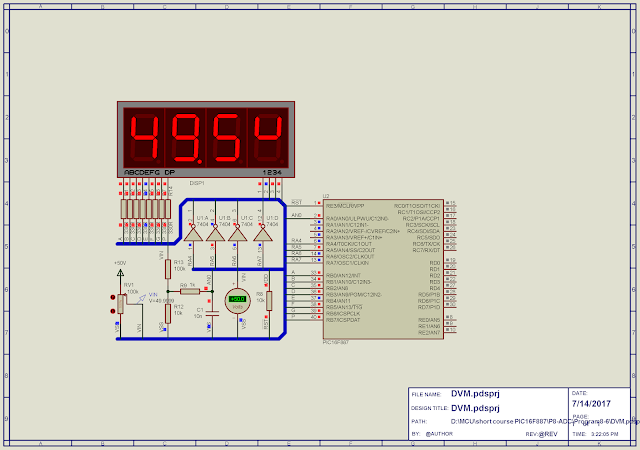
A DC +50V DVM using ADC of PIC16F887 MikroC - Program sample |
Reference circuit from Wikipedia |
Dividing factor depends on value of these two resistor that we can not give its detail and formula here. Using this method we can design a simple digital volt meter (DVM) with a maximum range of +50V DC.
In this example we select Z1 = 100kOhm and Z2 = 10kOhm. This circuit gives an output dividing factor of 0.09 at Vout. So whenever input voltage Vin = 50V then output voltage 50V * 0.09 that is around 5V, which is the maximum input voltage to ADC input channel.
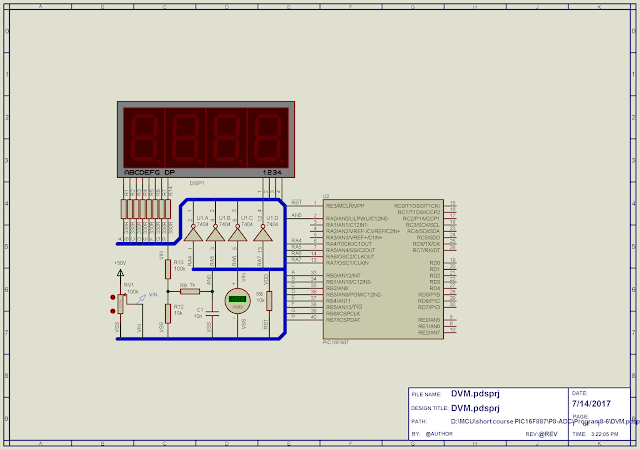
Circuit Diagram |
In this program timer0 is used to schedule ADC reading before it's converted to actual DC input voltage. Using its 8MHz internal oscillator source, timer0 interrupt creates a timer tick for scheduling ADC reading. Whenever the total tick equal to 30 it's a one second timing. Hence ADC reading is activated for every 30 timer0 tick (one second).
However multiplexing display doesn't use this timer tick due total lines of C source code.
MikroC source code:
#define STEP_SIZE 0.0048 #define ONE_SECOND 30 #define RATE 3 #define DIGIT1 PORTA.RA4 #define DIGIT2 PORTA.RA5 #define DIGIT3 PORTA.RA6 #define DIGIT4 PORTA.RA7 unsigned ADC_Value,V_Measure; float Voltage; char int_count; char LED[10]={0x3F,0x06,0x5B,0x4F,0x66,0x6D,0x7D,0x07,0x7F,0x6F}; bit ADC_RUN; void interrupt() { if(INTCON.T0IF) { int_count++; if(int_count==ONE_SECOND) { int_count=0; ADC_RUN=1; } } INTCON.T0IF=0; } void PORT_SETUP() { PORTA=0x00; PORTB=0x00; TRISA=0x01; // RA0 IS ANALOG IN PUT TRISB=0x00; // PORTB is OUTPUT ANSEL=0x01; // SELECT AN0 ANSELH=0x00; // OTHERS ARE DIGITAL IO OSCCON|=0x07; // SELECT 8MHz INT RC } void Timer0_Setup(){ OPTION_REG.T0CS=0; // SELECT FOSC/4 OPTION_REG.PSA=0; // SELECT TIMER0 PRESCALER OPTION_REG|=0x07; // SELECT 1:256 PRESCALER } void interrupt_setup() { INTCON.GIE=1; INTCON.T0IE=1; INTCON.T0IF=0; } void Read_Temp () { if(ADC_RUN=1) { ADC_Value=ADC_Get_Sample(0); // READ AN0 delay_ms(10); Voltage=ADC_Value*STEP_SIZE; // Convert to Decimal [Volt] } ADC_RUN=0; } void SSD() { V_Measure=Voltage*10/0.090; // convert Voltage to integer PORTB=LED[V_Measure/100]; DIGIT1=1; delay_ms(RATE); PORTA=0x00; PORTB=LED[(V_Measure%100)/10]|0x80; DIGIT2=1; delay_ms(RATE); PORTA=0x00; PORTB=LED[V_Measure%10]; DIGIT3=1; delay_ms(RATE); PORTA=0x00; PORTB=0x62; DIGIT4=1; delay_ms(RATE); PORTA=0x00; } void main() { ADC_Value=0; int_count=0; ADC_RUN=0; PORT_SETUP(); ADC_Init(); Timer0_Setup(); Interrupt_Setup(); while(1) { Read_Temp(); SSD(); } }
No comments:
Post a Comment