Friday, January 8, 2021

PIC16F887 Timer0 Interrupt Driven Display

Introduction

Since timer interrupt runs in background of microcontroller program. We can use this feature to create timing tick activating some tasks.

Multiplexing a display requires an activating time ranging around 5ms for each digit to display properly. More digits require more time in milliseconds. Other remaining tasks in microcontroller program need to wait until display driving finished. Embedded controller program designed using this method is not responsive.

00:00 / 00:00

Using timer0 interrupt, a timing tick can activate each digit of multiplexing display regularly. Display timing doesn't consume main program loop timing. Main program just operate other remaining tasks. Any program written using interrupt is flexible.
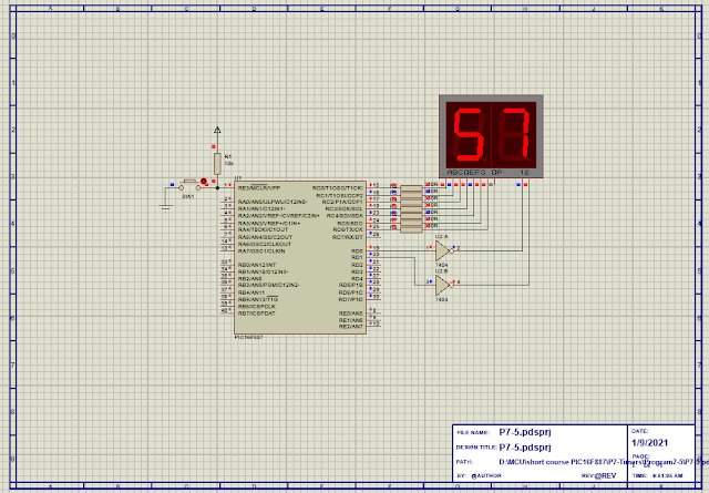
PIC16F887 Timer0 Interrupt Driven Display
Simulation sample of this program

Timer0 Interrupt Programming

This example program multiplex a two-digit display using timer0 interrupt timing ticks. Each digit will be activated for 5ms. It's a free running timer that counts up from 0 to 59 seconds before it resets.


Timer0 clock prescaler is assigned to 1:256. Number of ticks per second is 30. Display type is common cathode. We just use an inverting buffer here due to simulation problem.
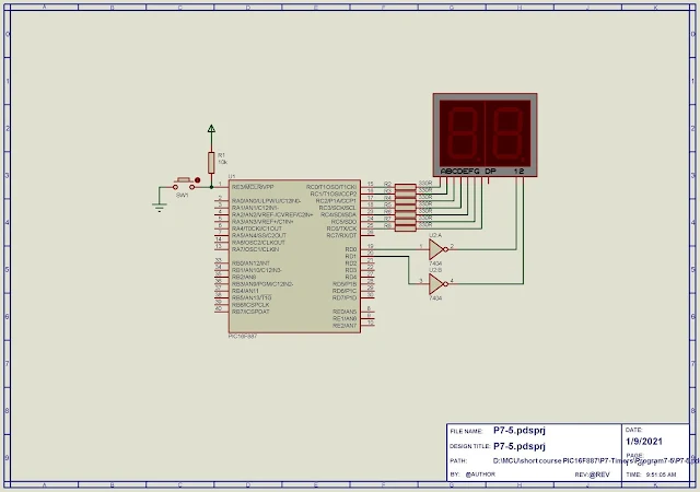
PIC16F887 Timer0 Interrupt Driven Display
Schematic Diagram


This controller pulse from its 8MHz internal oscillator.

#define Ticks_Per_Second 30
#define RATE 5
char LED[10]={0x3F,0x06,0x5B,0x4F,0x66,0x6D,0x7D,0x07,0x7F,0x6F};
char interrupt_count;
char s1,s10;
void interrupt() {
if(INTCON.T0IF) interrupt_count++;
if(interrupt_count==Ticks_Per_Second)
{ s1++;
interrupt_count=0;
if(s1==10) {s10++; s1=0; }
if(s10==6) s10=0;
}
INTCON.T0IF=0;
}
void PORT_SETUP() {
PORTC=0x00; // Clear PORTC
PORTD=0x00; // Clear PORTD
TRISD=0x00; // PORTD AS OUTPUT
TRISC=0x00; // PORTC AS OUTPUT
}
void timer_setup() {
OPTION_REG.T0CS=0; // SELECT INTERNAL SOURCE
OPTION_REG.PSA=0; // PRESCALER ASSIGNED TO TMR0
OPTION_REG|=0x07; // SELECT 1:256 PRESCALER
}
void interrupt_setup() {
INTCON.GIE=1; // Enable Global Interrut
INTCON.T0IE=1; // ENABLE TIMER0 INTERRUPT
INTCON.T0IF=0; // CLEAR FLAG
}
void SSD(){
PORTC=LED[s10];
PORTD=0x01;
delay_ms(RATE);
PORTD=0x00;
PORTC=LED[s1];
PORTD=0x02;
delay_ms(RATE);
PORTD=0x00;
}
void main() {
s1=s10=0;
interrupt_count=0;
OSCCON|=0x70;
PORT_SETUP();
timer_SETUP();
interrupt_setup();
while(1) SSD();
}
view raw Program7-5.c hosted with ❤ by GitHub

Click here to download its source file.


No comments:

Post a Comment

Labels

ADC (10) Analog (14) Arduino (12) Atmega16 (19) Audio (2) AVR (20) Charger (1) Cortex-M0 (1) Counter (10) CPLD (25) Digital I/O (22) Display (34) EEPROM (2) Environment Sensor (1) esp8266 (2) Experiment Board (10) I2C (4) Interrupt (7) LCD (1) LDmicro (29) measurement and instrumentation (7) Microchip Studio (3) MikroC (1) One-Shot (3) OpAmp (1) PCB (31) PIC16 Microcontrollers (16) PIC16F877A (2) PIC16F887 MikroC (22) PLC (35) PWM (11) Regulator (1) RTC (2) Sensor (8) Shift Registers (5) SPI (5) Timer (34) UART (2) ultra-sonic sensor (1) USB (1) VHDL (21) xc8 (1) XC95108 (9) XC9536 (15) XC9572 (1) Xilinx (23) Xilinx ISE (22)