Introduction
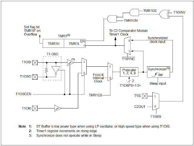
Additionally to Timer0, PIC16F887 has an 16-bit timer - Timer1. This timer is more advanced than Timer0. It has some additional features over Timer0
- Optional LP oscillator
- Synchronous or asynchronous operation
- Gate mode
- Interrupt on overflow
- Capture/compare function, etc.
 |
| Block diagram of Timer1 |
There are some registers to Timer1.
 |
| Registers relate to Timer1 |
Timer1 Control Register (T1CON) set the overall operations of Timer1.
 |
| Timer1 Control Register (T1CON) |
Timer1 Application of Ultra-Sonic Range Measurement
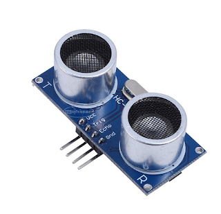
An application of timer is pulse width measurement of external incoming event. For instance Ultrasonic Ranging Module HC-SR04, is a low cost popular range measurement for electronics hobbyist.
 |
| Popular HC-SR04 sample (Ali Express) |
This module is a non-contact measuring type of sensor. It uses sounds wave traveling in space, along with its echo signal to get the distance. Measurement ranges from 4cm to 4 meters.
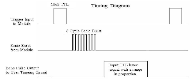
To make its measurement works properly the programmer must check its timing diagram.
 |
| Timing Diagram |
It has a formula to measure range in term of receiving pulse width.
Range = (high level time)*(velocity)/2
Velocity of sound is 340m/s.
In short form we use only high time in us,
Range (in cm) = high level time (in us) / 58
To get range in Inch,
Range (in inch) = high level time (in us) / 148
Programming in MikroC
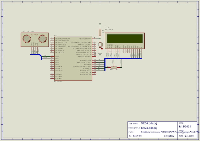
System has HC-SR04 as its input. A character LCD output displays sampling range measurement. PIC16F887 controller uses its internal 8MHz oscillator.
Timer1 measure echo signal from HC-SR04 input to RD1. RD1 of PIC16F887 is trigger pin initiating range measurement of sensor. Prescaler is assigned to 1:2 to get a 1us timing.
 |
| Schematic Diagram |
MikroC source code:
Click here to download its zip file.
No comments:
Post a Comment