Introduction
Timer0 module is able to trigger interrupt even it's operate in timer or counter mode. It must be enabled and handled in ISR to get full advantage.
Timer0 interrupt is a thread written in ISR that doesn't need to be polled in main program loop. It's automatically called whenever its interrupt flag is set, then it's executed and automatically return to previous program context.
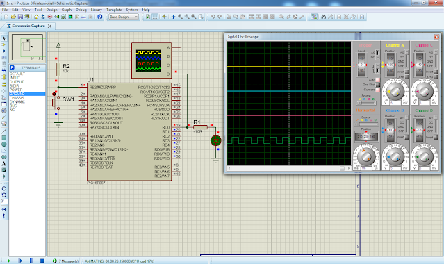
Timer interrupt is useful for creating a timer tick that schedule tasks in microcontroller program. However we use this advantage to create a simple 1ms timing delay seeing its effect. It's other than an output square wave.
 |
| Simulation sample of this programming example |
Program Configuration
Main Program
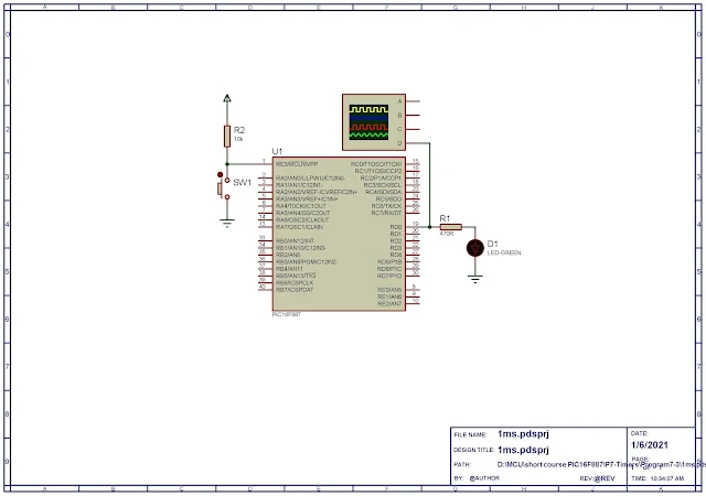
In main program setting up, RD0 of Port D is output pin. It must be configure to output direction in its corresponding TRISD register.
Oscillator is driven from PIC16F887 internal RC oscillator using its maximum 8MHz frequency.
Timer0 module is selected to operate in timer mode with 1:2 prescaler.
Global interrupt, Timer0 interrupt must be enabled. It's interrupt flag and Timer0 register must be cleared first.
Main program loop stay idle as there's no additional code to handle.
Interrupt Service Routine
To handle interrupt, targeting interrupt source must be written in interrupt service routine (ISR). Timer0 interrupt flag must be tested first and clear before remaining code.
void interrupt() {
if(INTCON.T0IF) {
counter++;
if(counter==Ticks_Per_Ms)
{ counter=0; OUTPUT^=1; }
}
INTCON.T0IF=0;
}
The void interrupt() is MikroC compiler's reserve keyword used for ISR. It's unique for all interrupt source in Mid-Range PIC16F887 microcontroller.
Creating Timer Tick
PIC executing speed is,
Fins = (Fosc)/4 = (8MHz)/4 = 2MHz.
Its executing period is,
Tins = 1/(Fins) = 1/(2MHz) = 500ns.
Timer0 pulses at 1:2 rate. It's increment for every,
Ttimer0 = 2 * 500ns = 1us.
Timer0 overflows when,
256 * 1us = 256us.
If it overflows for four time it create a timing tick of about 1ms.
4 * 256us = 1024us.
MikroC Program
C program lists about is written for this programming example.
Click here to download this example.
Diagram lists below is its full schematic.
 |
| Schematic diagram |
No comments:
Post a Comment