Tuesday, January 12, 2021

PIC16F887 Timer1 and Ultra Sonic Range Measurement Application

Introduction

Additionally to Timer0, PIC16F887 has an 16-bit timer - Timer1. This timer is more advanced than Timer0. It has some additional features over Timer0

  • Optional LP oscillator
  • Synchronous or asynchronous operation
  • Gate mode
  • Interrupt on overflow
  • Capture/compare function, etc.
PIC16F887 Timer1 and Ultra Sonic Range Measurement Application
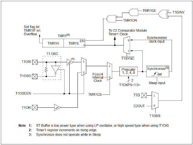
Block diagram of Timer1

 There are some registers to Timer1.

PIC16F887 Timer1 and Ultra Sonic Range Measurement Application
Registers relate to Timer1


 Timer1 Control Register (T1CON) set the overall operations of Timer1.

PIC16F887 Timer1 and Ultra Sonic Range Measurement Application
Timer1 Control Register (T1CON)

 Timer1 Application of Ultra-Sonic Range Measurement

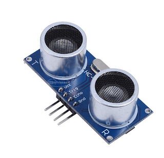
An application of timer is pulse width measurement of external incoming event. For instance Ultrasonic Ranging Module HC-SR04, is a low cost popular range measurement for electronics hobbyist.


PIC16F887 Timer1 and Ultra Sonic Range Measurement Application
Popular HC-SR04 sample (Ali Express)

This module is a non-contact measuring type of sensor. It uses sounds wave traveling in space, along with its echo signal to get the distance. Measurement ranges from 4cm to 4 meters.

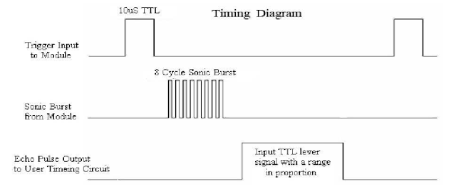
To make its measurement works properly the programmer must check its timing diagram.  
PIC16F887 Timer1 and Ultra Sonic Range Measurement Application
Timing Diagram

 It has a formula to measure range in term of receiving pulse width.

Range = (high level time)*(velocity)/2

Velocity of sound is 340m/s.

In short form we use only high time in us,

Range (in cm) = high level time (in us) / 58 

To get range in Inch,

Range (in inch) = high level time (in us) / 148

Programming in MikroC

System has HC-SR04 as its input. A character LCD output displays sampling range measurement. PIC16F887 controller uses its internal 8MHz oscillator.

Timer1 measure echo signal from HC-SR04 input to RD1. RD1 of PIC16F887 is trigger pin initiating range measurement of sensor. Prescaler is assigned to 1:2 to get a 1us timing.
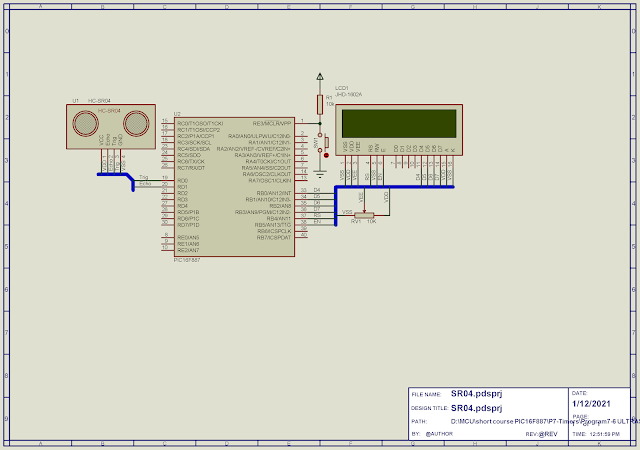
PIC16F887 Timer1 and Ultra Sonic Range Measurement Application
Schematic Diagram


 MikroC source code:


Click here to download its zip file.
Friday, January 8, 2021

PIC16F887 Timer0 Interrupt Driven Display

Introduction

Since timer interrupt runs in background of microcontroller program. We can use this feature to create timing tick activating some tasks.

Multiplexing a display requires an activating time ranging around 5ms for each digit to display properly. More digits require more time in milliseconds. Other remaining tasks in microcontroller program need to wait until display driving finished. Embedded controller program designed using this method is not responsive.

Using timer0 interrupt, a timing tick can activate each digit of multiplexing display regularly. Display timing doesn't consume main program loop timing. Main program just operate other remaining tasks. Any program written using interrupt is flexible.

PIC16F887 Timer0 Interrupt Driven Display
Simulation sample of this program

Timer0 Interrupt Programming

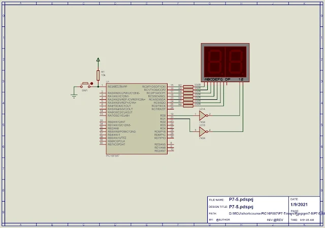
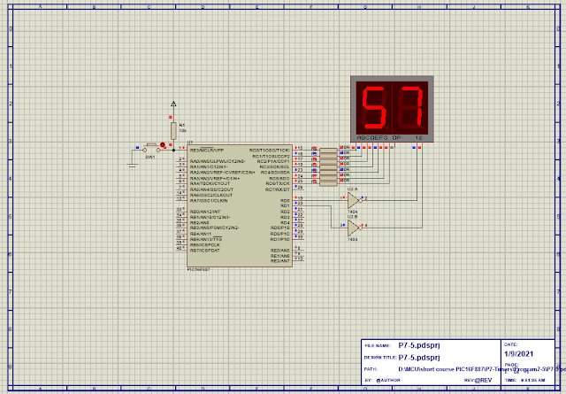
This example program multiplex a two-digit display using timer0 interrupt timing ticks. Each digit will be activated for 5ms. It's a free running timer that counts up from 0 to 59 seconds before it resets.


Timer0 clock prescaler is assigned to 1:256. Number of ticks per second is 30. Display type is common cathode. We just use an inverting buffer here due to simulation problem.

PIC16F887 Timer0 Interrupt Driven Display
Schematic Diagram


This controller pulse from its 8MHz internal oscillator.

Click here to download its source file.


Wednesday, January 6, 2021

PIC16F887 Timer0 Creating Delay Function in MikroC

Introduction

In previous post of Timer0 interrupt programming, we use its interrupt advantage to create a timer tick in a range of milli second. We can decorate some more features over this capability.

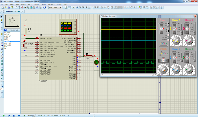
A precise timing delay function can be created using timer0 interrupt programming. In this example we create a delay function from the existing 1ms-delay routine that it was written in previous example

PIC16F887 Timer0 Creating Delay Function in MikroC
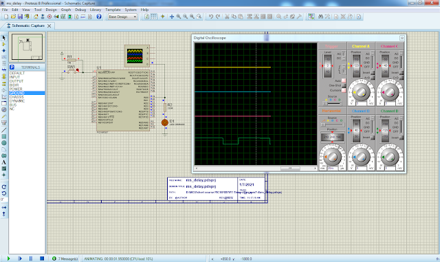
Program simulation sample


Programming

Delay function created by adding more routine that rely on free running counter in the ISR coding of Timer0 interrupt.

void ms_delay(unsigned count) {
     while(ms_count<count);
      ms_count=0;

}

There is no change in source code but it excepts only one additional routine that handle timing delay. 

PIC16F887 Timer0 Creating Delay Function in MikroC
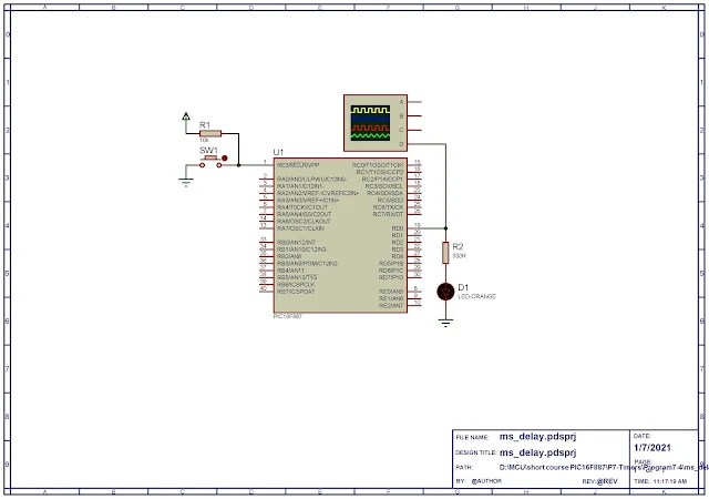
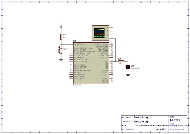
Schematic Diagram

Program in MikroC


Click here to download source file.


Tuesday, January 5, 2021

PIC16F887 Timer0 Interrupt Programming in MikroC

Introduction

Timer0 module is able to trigger interrupt even it's operate in timer or counter mode. It must be enabled and handled in ISR to get full advantage. 

Timer0 interrupt is a thread written in ISR that doesn't need to be polled in main program loop. It's automatically called whenever its interrupt flag is set, then it's executed and automatically return to previous program context.

Timer interrupt is useful for creating a timer tick that schedule tasks in microcontroller program. However we use this advantage to create a simple 1ms timing delay seeing its effect. It's other than an output square wave.

PIC16F887 Timer0 Interrupt Programming in MikroC
Simulation sample of this programming example

Program Configuration

Main Program

In main program setting up, RD0 of Port D is output pin. It must be configure to output direction in its corresponding TRISD register.

Oscillator is driven from PIC16F887 internal RC oscillator using its maximum 8MHz frequency. 

Timer0 module is selected to operate in timer mode with 1:2 prescaler.

Global interrupt, Timer0 interrupt must be enabled. It's interrupt flag and Timer0 register must be cleared first.

Main program loop stay idle as there's no additional code to handle.

Interrupt Service Routine 

To handle interrupt, targeting interrupt source must be written in interrupt service routine (ISR). Timer0 interrupt flag must be tested first and clear before remaining code.

void interrupt() {
     if(INTCON.T0IF) {
        counter++;
        if(counter==Ticks_Per_Ms)
           { counter=0; OUTPUT^=1; }
           }
     INTCON.T0IF=0;    
}

The void interrupt() is MikroC compiler's reserve keyword used for ISR. It's unique for all interrupt source in Mid-Range PIC16F887 microcontroller.


Creating Timer Tick 

PIC executing speed is,

Fins = (Fosc)/4 = (8MHz)/4 = 2MHz.

Its executing period is,

Tins = 1/(Fins) = 1/(2MHz) =  500ns.

Timer0 pulses at 1:2 rate. It's increment for every,

Ttimer0 = 2 * 500ns = 1us.

Timer0 overflows when,

256 * 1us = 256us.

If it overflows for four time it create a timing tick of about 1ms.

4 * 256us = 1024us. 

MikroC Program

C program lists about is written for this programming example.


Click here to download this example.

Diagram lists below is its full schematic.

PIC16F887 Timer0 Interrupt Programming in MikroC
Schematic diagram


PIC16F887 Timer0 in timer mode MikroC

Introduction

As mentioned earlier, Timer0 works in either timer and counter mode. Timer0 Clock Select bit toggle between these two modes. Implementation of timer of a microcontroller has already described in previous post.

In this programming example of using Timer0 module, timer creates a time tick that's a square wave output on a microcontroller digital output pin.

Configuration

Timer0 module of PIC16F887 is configured to operate in timer mode. Prescaler is assigned to WDT to get 1:1 ratio.

Microcontroller clock is its 8MHz internal oscillator. Microcontroller executing speed is,

Finstruction = Fosc/4 = (8MHz)/4 = 2MHz.

Microcontroller instruction executing cycle is,

Tinstruction = 1/2MHz =  500ns.

Input clock pulse is directly drive to Timer0 module. Timer0 overflow time is,

Timer0overflow = 256 * 500ns = 128us.

Each time Timer0 overflow RD0 of Port D toggles, creating an output square wave. The period of square wave is,

Tinterrupt = 2 * 128us = 256us.

Its frequency is,

1 / (256us) = 3906Hz.

Programming for Timer0

This programming example is simulated using Proteus.


PIC16F887 Timer0 in timer mode MikroC
Schematic Diagram


MikroC program lists below,

  1. #define OUTPUT PORTD.RD0
  2.  
  3. void main() {
  4. PORTD=0x00; // CLEAR PORTD
  5. TRISD=0x00; // SET PORTD AS OUTPUT
  6. OSCCON|=0x70; // SELECT INTERNAL OSCILLATOR 8MHz
  7. OPTION_REG.T0CS=0; // SELCT INTERNAL SOURCE
  8. OPTION_REG.PSA=1; // Prescaler Assigned to WDT
  9. OPTION_REG&=0xF8 ; // SELECT 1:1 Prescaler
  10. TMR0=0; // CLEAR TIMER0
  11. while(1)
  12. if(INTCON.T0IF){
  13. INTCON.T0IF=0;
  14. PORTD^=1;
  15. }
  16. }

Click here to download this programming example.  


Labels

ADC (10) Analog (14) Arduino (12) Atmega16 (19) Audio (2) AVR (20) Charger (1) Cortex-M0 (1) Counter (10) CPLD (25) Digital I/O (22) Display (34) EEPROM (2) Environment Sensor (1) esp8266 (2) Experiment Board (10) I2C (4) Interrupt (7) LCD (1) LDmicro (29) measurement and instrumentation (7) Microchip Studio (3) MikroC (1) One-Shot (3) OpAmp (1) PCB (31) PIC16 Microcontrollers (16) PIC16F877A (2) PIC16F887 MikroC (22) PLC (35) PWM (11) Regulator (1) RTC (2) Sensor (8) Shift Registers (5) SPI (5) Timer (34) UART (2) ultra-sonic sensor (1) USB (1) VHDL (21) xc8 (1) XC95108 (9) XC9536 (15) XC9572 (1) Xilinx (23) Xilinx ISE (22)