Sunday, September 27, 2020

PLC piecewise linear table instruction to convert A/D value into PWM duty cycle

In the previous post, I have show to use piecewise linear table to convert between ADC value to analog voltage value. The advantage of this instruction is that the programmer could map between two value without putting any math equation into the PLC ladder diagram program.

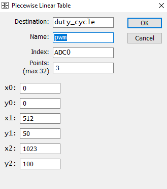
Here, I use this instruction to map the A/D converter digital value into the PWM duty cycle that it will adjust the speed of a DC motor. I create a piecewise linear table with three points on the graph A(x0,y0) B(x1,y1) and C(x2,y2).
PLC piecewise linear instruction to convert A/D value into PWM duty cycle
A piecewise linear table that return a duty cycle value in term of the ADC0.

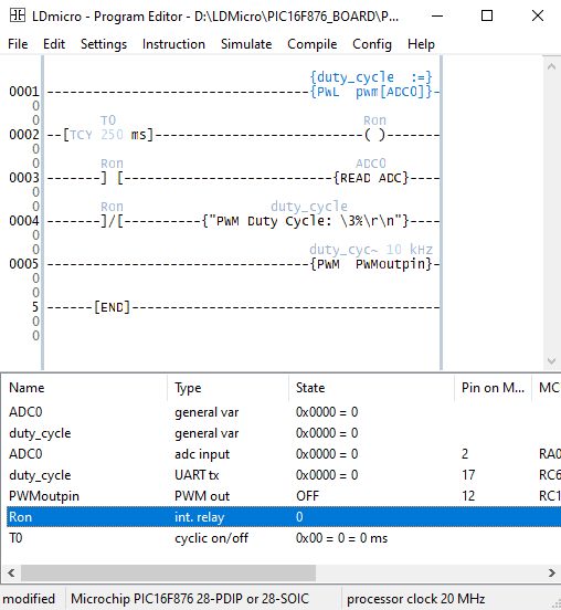
The main ladder diagram program keeps track of three main tasks:
  1. Reading the A/D converter value and converts it to the PWM duty cycle value via a piecewise linear table.
  2. Sending the current PWM duty cycle to the host PC via UART terminal
  3. Adjusting the motor speed via its PWM duty cycle.

PLC piecewise linear instruction to convert A/D value into PWM duty cycle
The Ladder Diagram Program

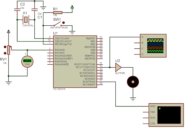
I selected PIC16F876 due a the ease of use.
PLC piecewise linear instruction to convert A/D value into PWM duty cycle
Schematic Diagram

Click here to download this ladder diagram example.


No comments:

Post a Comment

Labels

ADC (10) Analog (14) Arduino (12) Atmega16 (19) Audio (2) AVR (20) Charger (1) Cortex-M0 (1) Counter (10) CPLD (25) Digital I/O (22) Display (34) EEPROM (2) Environment Sensor (1) esp8266 (2) Experiment Board (10) I2C (4) Interrupt (7) LCD (1) LDmicro (29) measurement and instrumentation (7) Microchip Studio (3) MikroC (1) One-Shot (3) OpAmp (1) PCB (31) PIC16 Microcontrollers (16) PIC16F877A (2) PIC16F887 MikroC (22) PLC (35) PWM (11) Regulator (1) RTC (2) Sensor (8) Shift Registers (5) SPI (5) Timer (34) UART (2) ultra-sonic sensor (1) USB (1) VHDL (21) xc8 (1) XC95108 (9) XC9536 (15) XC9572 (1) Xilinx (23) Xilinx ISE (22)