 |
| Piece wise linear application with ADC reading |
The graph above shows a function of voltage vs its ADC reading. For example,
- f(0) = 0
- f(512) = 2.5 V
- f(1023) = 5 V
Now let move back to LDMicro ladder diagram, the symbol of piece wise linear instruction shown below.
 |
| PWL ladder diagram instruction symbol |
The property of the instruction allow us to set the name, number of points etc.
 |
| PWL instruction property |
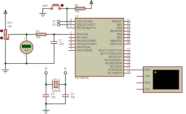
For a simple example, I use this instruction to read the analog value fed to RA0 of the PLC and send it over the UART to the host PC.
 |
| PWL ladder diagram example |
PIC16F876 is selected as a CPU of this PLC, clocks at 20 MHz to get its maximum computing performance.
- The PWL table created with only two points. It output a decimal analog voltage, volt.
- An internal output coil Rstate active for every 600 mS by a timer tick created by a cyclic on/off T0. It activates the ADC instruction to read the analog input voltage fed to RA0 of the PLC MCU.
- The UART instruction activated by the Rstate to send the analog voltage reading value to the host PC via UART.
 |
| Simulation schematic diagram |
Click here to download this ladder diagram example in zip file.

No comments:
Post a Comment