 |
| The OSL timing diagram |
This instruction is useful in the case that the user needs to trigger the action on the falling to low level of the input signal.
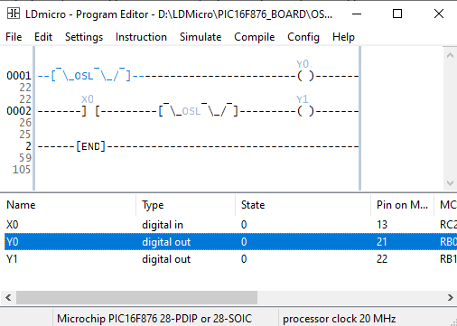
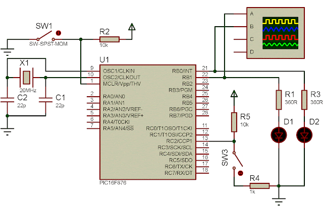
In the following example, we create a sample monitoring of this instruction. Whenever the user switch the input contact to the ground, the contact makes a input false signal to the OSL. This OSL again trigger a low level pulse of one PLC scan cycle of 10 mS.
 |
| The OSL ladder diagram example |
The output coil Y0 is normally output true in the overall PLC program. The output coil Y1 outputs true when there's nothing happen.
 |
| Circuit Diagram |
Click here to download the zip file of this working example.

No comments:
Post a Comment