Friday, September 25, 2020

PLC one shot rising ladder diagram instruction

In the PLC ladder diagram a one shot instruction creates a one shot signal output. For the one shot rising OSF instruction, it output a high pulse for one PLC cycle time - for example 10 mS, whenever its input true. This output pulse only create one's until the system is reset.
The one shot rising instruction symbol

This instruction is an auxiliary to other instruction in the same rung. It's place in front of other instructions to make them run only once when the program started.


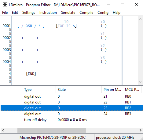
Let take a look at a simple ladder diagram example. 
PLC one shot rising ladder diagram instruction
OSF ladder diagram example program

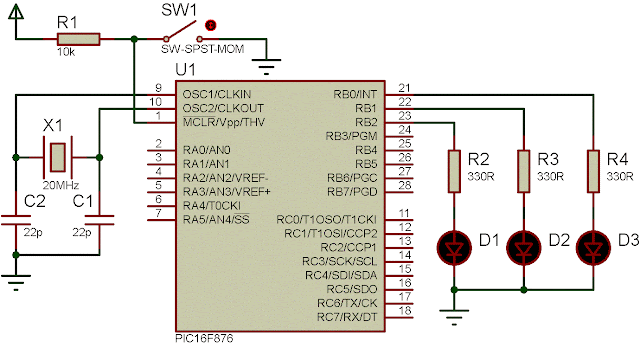
An OSF activate the turn off delay T0F that create a high delay time for 10 second before it's fall. So the output coil Y0 turned on for only 10 second in the PLC program.


PLC one shot rising ladder diagram instruction
The ladder diagram programming example of the OSF

Click here to download the zip file of this working example.


No comments:

Post a Comment

Labels

ADC (10) Analog (14) Arduino (12) Atmega16 (19) Audio (2) AVR (20) Charger (1) Cortex-M0 (1) Counter (10) CPLD (25) Digital I/O (22) Display (34) EEPROM (2) Environment Sensor (1) esp8266 (2) Experiment Board (10) I2C (4) Interrupt (7) LCD (1) LDmicro (29) measurement and instrumentation (7) Microchip Studio (3) MikroC (1) One-Shot (3) OpAmp (1) PCB (31) PIC16 Microcontrollers (16) PIC16F877A (2) PIC16F887 MikroC (22) PLC (35) PWM (11) Regulator (1) RTC (2) Sensor (8) Shift Registers (5) SPI (5) Timer (34) UART (2) ultra-sonic sensor (1) USB (1) VHDL (21) xc8 (1) XC95108 (9) XC9536 (15) XC9572 (1) Xilinx (23) Xilinx ISE (22)