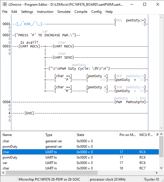
The UART terminal of the host PC receives the character command from the user to increase/decrease the duty cycle. I use letter 'P' to increase the duty cycle and letter 'N' to decrease the duty cycle.
There some others remanding instruction that I don't want to show any detail here due to the previous post's explanation.
 |
| Ladder diagram example |
The initial set up assigns the duty cycle to 0 - there's no output power. A UART terminal prompt the user once in how to adjust the duty cycle.
Once the character command is prompted the PWM duty cycle is adjust within the step of 10% in duty cycle.
 |
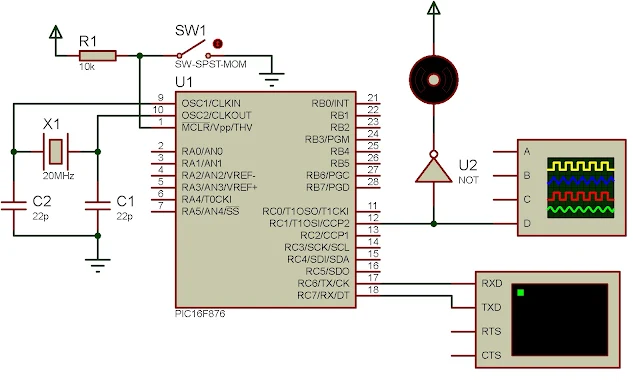
| The schematic diagram |
Click here to download the zip file of this working ladder diagram example.
No comments:
Post a Comment