Friday, September 25, 2020

PLC toggle type coil ladder diagram instruction

In the PLC ladder diagram, a coil is classified into many types as shown in the picture below.

Many options of coil types selection.

As we can see in the picture below a coil could be an internal relay, an output pin on MCU or a Modbus. There are five different types of coil. Here we select the T-trigger (T) type. The letter T means 'toggle'.

A T-trigger coil changes (toggles) its output logic state whenever it's input change from low to high.

Let look at very simple example, I use an input contact to change the logic state of the output coil.
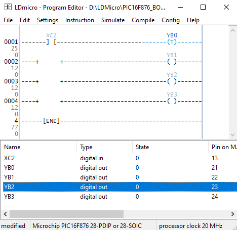
PLC toggle type coil ladder diagram instruction
Toggle type coil ladder diagram example

When the contact XC2 changes from false to true, the output coil changes its logic state.


We can make a circuit simulation in Proteus to verify the result.
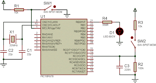
PLC toggle type coil ladder diagram instruction
Ladder diagram program example

This program could run on an 8-pin PIC16F629 for convenience. My YouTube video show about a testing program on my DIY PLC board I made a few years ago.


Click here to download the zip file of this ladder diagram example.

No comments:

Post a Comment

Labels

ADC (10) Analog (14) Arduino (12) Atmega16 (19) Audio (2) AVR (20) Charger (1) Cortex-M0 (1) Counter (10) CPLD (25) Digital I/O (22) Display (34) EEPROM (2) Environment Sensor (1) esp8266 (2) Experiment Board (10) I2C (4) Interrupt (7) LCD (1) LDmicro (29) measurement and instrumentation (7) Microchip Studio (3) MikroC (1) One-Shot (3) OpAmp (1) PCB (31) PIC16 Microcontrollers (16) PIC16F877A (2) PIC16F887 MikroC (22) PLC (35) PWM (11) Regulator (1) RTC (2) Sensor (8) Shift Registers (5) SPI (5) Timer (34) UART (2) ultra-sonic sensor (1) USB (1) VHDL (21) xc8 (1) XC95108 (9) XC9536 (15) XC9572 (1) Xilinx (23) Xilinx ISE (22)