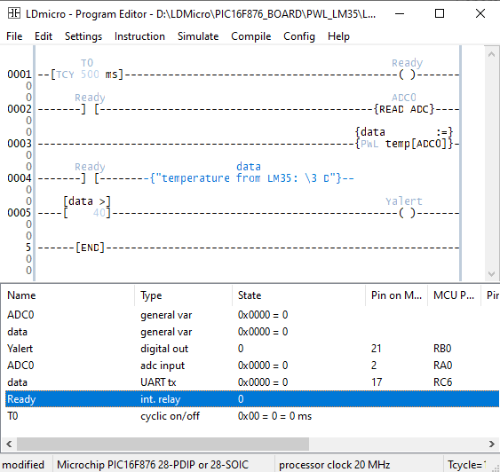
- cyclic on/off timer
- contact and coil
- read A/D converter
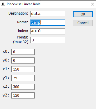
- piecewise linear table
- if greater than instruction
- formatted string over UART
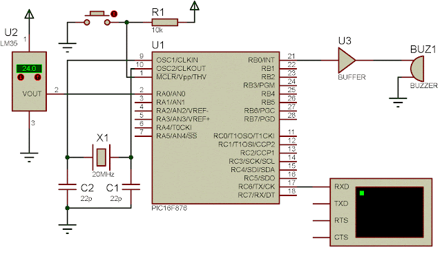
In this example, the PLC reads an analog temperature converted by LM35 analog temperature sensor. A buzzer will alarm whenever the temperature exceed 40 degree Celsius. Temperature data sent over the UART terminal to the host PC.
 |
| A commercial sample of LM35 from an online market place. |
 |
| Ladder diagram example |
Cyclic on/off timer T0 activate the internal output coil Ready for every one second. This coil command the A/D converter read instruction ADC0. It also command the PLC to sent data over the UART terminal to the host PC.
Piecewise linear table create the temperature data table corresponding to the analog voltage value converted by LM35 analog temperature sensor.
 |
| The temp is a function of ADC0. This table created by three points. It return a temperature data between 0 and 150 degree Celsius. |
A comparison instruction if greater than compare the analog temperature with 40 degree Celsius, a preset value made by the programmer. If the temperature exceed 40 degree Celsius it will output true turning the alarm buzzer.
 |
| Schematic diagram |
An alarm buzzer could be any type - a simple active 5V buzzer or a active 12 V buzzer. Selecting the right buffer driver depends on the user. There are a lot of driver available in the online market place. I don't want to specify them here.
Click here to download the zip file of this ladder diagram example.
No comments:
Post a Comment