Thursday, September 24, 2020

PLC piecewise linear table and 7-segments instruction

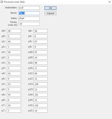
With the piecewise linear table again, I use this instruction to create a map of characters from 0 to F presenting a hexadecimal values.

The host PC UART terminal send the ASCII character within a range of 0 to 15 to the PLC. These value will be converted by the PLC piecewise linear table instruction before it's sent to the 7-Segment display.
PLC piecewise linear table and 7-segments instruction
Piecewise linear table instruction setting

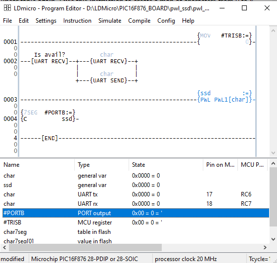
The ladder diagram program made up of a few rungs as listed below.
PLC piecewise linear table and 7-segments instruction
Ladder diagram example

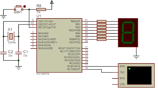
The PLC hardware made up of a few components, a 7-segment display, clock and reset circuit. We assume that the user use a USB-serial converter to make a communication between the PLC and the host PC.


PLC piecewise linear table and 7-segments instruction
Schematic diagram

I made a photo of sample of the running program of PLC.


A sample of running program. The UART send a list of character ended with letter 'A'.

Click here to download the zip file of this ladder diagram example.

No comments:

Post a Comment

Labels

ADC (10) Analog (14) Arduino (12) Atmega16 (19) Audio (2) AVR (20) Charger (1) Cortex-M0 (1) Counter (10) CPLD (25) Digital I/O (22) Display (34) EEPROM (2) Environment Sensor (1) esp8266 (2) Experiment Board (10) I2C (4) Interrupt (7) LCD (1) LDmicro (29) measurement and instrumentation (7) Microchip Studio (3) MikroC (1) One-Shot (3) OpAmp (1) PCB (31) PIC16 Microcontrollers (16) PIC16F877A (2) PIC16F887 MikroC (22) PLC (35) PWM (11) Regulator (1) RTC (2) Sensor (8) Shift Registers (5) SPI (5) Timer (34) UART (2) ultra-sonic sensor (1) USB (1) VHDL (21) xc8 (1) XC95108 (9) XC9536 (15) XC9572 (1) Xilinx (23) Xilinx ISE (22)