- Piecewise linear table
- shift register
- UART
- Counter
- And one shot
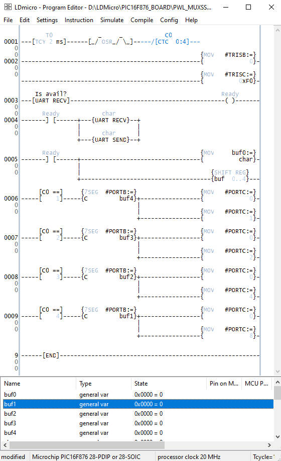
Now we combine, these instruction to make a simple example. In this example the user send the ASCII characters over the UART terminal to the PLC.
 |
| Ladder diagram example |
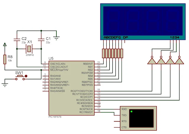
A circular counter activates the four digits multiplexed displays. The display port is PORTC. Each digit becomes active for 2 mS.
A set of UART instructions send and receive the characters between the host PC and the PLC.
A five stages shift register, receives the character sent from UART before it sends to the multiplexed display.
 |
| Schematic Diagram |
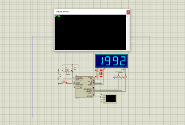
The picture below is a sample of program simulation.
 |
| A sample of program |
Click here to download the ladder diagram example.
No comments:
Post a Comment