Monday, January 29, 2024

XC95108 Two-Digit 7-Segment Shift Registers VHDL Example

In previous post, I use the XC95108 to make a 16-bit LED shift registers. It's similar to the SNHC164 serial in parallel out shift registers chip. Using a CPLD and VHDL code we can customize any digital circuit. 

XC95108 Two-Digit 7-Segment Shift Registers VHDL Example
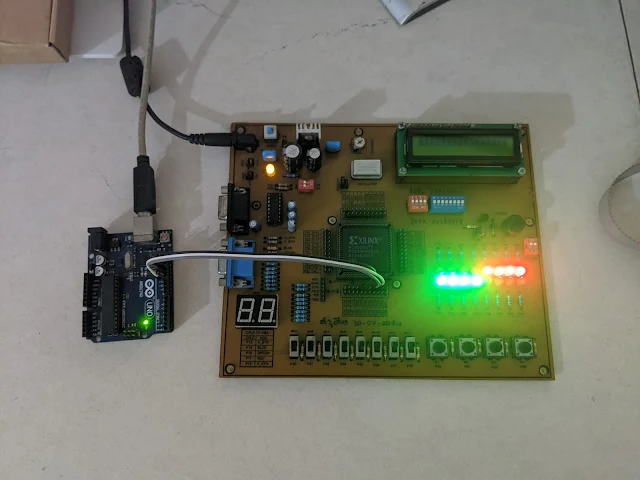
The Arduino Uno and the XC95108 CPLD Prototype Board 

Here I make another serial in parallel out shift registers chip that's similar to the SN74HC595. It's a two-digit 7-Segment display driver with SPI interface. It has the following I/O:

  • Reset (RST) input (active low)
  • Enable (EN) input for data latching
  • Serial Data In (MOSI)
  • Serial Clock In (SCK)
  • 7-Segment Digit 1 (LEDA)
  • and 7-Segment Digit 2 (LEDB).

The 7-Segment display is a two-digit 0.56" red common cathode display. The shift registers process is synchronize with the logic high level of serial clock input (SCK). Shift registers data are latched into the output LED ports at the high to low transition of the EN (Enable) pin.

  1. ----------------------------------------------------------------------------------
  2. -- Company:
  3. -- Engineer:
  4. --
  5. -- Create Date: 08:29:52 01/30/2024
  6. -- Design Name:
  7. -- Module Name: spi_7_2 - Behavioral
  8. -- Project Name:
  9. -- Target Devices:
  10. -- Tool versions:
  11. -- Description:
  12. --
  13. -- Dependencies:
  14. --
  15. -- Revision:
  16. -- Revision 0.01 - File Created
  17. -- Additional Comments:
  18. --
  19. ----------------------------------------------------------------------------------
  20. library IEEE;
  21. use IEEE.STD_LOGIC_1164.ALL;
  22.  
  23. -- Uncomment the following library declaration if using
  24. -- arithmetic functions with Signed or Unsigned values
  25. --use IEEE.NUMERIC_STD.ALL;
  26.  
  27. -- Uncomment the following library declaration if instantiating
  28. -- any Xilinx primitives in this code.
  29. --library UNISIM;
  30. --use UNISIM.VComponents.all;
  31.  
  32. entity spi_7_2 is
  33. Port ( RST : in STD_LOGIC;
  34. EN : in STD_LOGIC;
  35. SCK : in STD_LOGIC;
  36. MISO : in STD_LOGIC;
  37. LEDA : out STD_LOGIC_VECTOR (7 downto 0);
  38. LEDB : out STD_LOGIC_VECTOR (7 downto 0));
  39. end spi_7_2;
  40.  
  41. architecture Behavioral of spi_7_2 is
  42. SIGNAL REGA,REGB: STD_LOGIC_VECTOR(7 DOWNTO 0);
  43. begin
  44. PROCESS(SCK,RST,EN)
  45. BEGIN
  46. IF(RST='0') THEN REGA<=x"00"; REGB<=x"00";
  47. ELSIF(SCK'EVENT AND SCK='1') THEN
  48. -- REGISTER A
  49. REGA(0)<=MISO;
  50. REGA(1)<=REGA(0);
  51. REGA(2)<=REGA(1);
  52. REGA(3)<=REGA(2);
  53. REGA(4)<=REGA(3);
  54. REGA(5)<=REGA(4);
  55. REGA(6)<=REGA(5);
  56. REGA(7)<=REGA(6);
  57.  
  58. -- REGISTER B
  59. REGB(0)<=REGA(7);
  60. REGB(1)<=REGB(0);
  61. REGB(2)<=REGB(1);
  62. REGB(3)<=REGB(2);
  63. REGB(4)<=REGB(3);
  64. REGB(5)<=REGB(4);
  65. REGB(6)<=REGB(5);
  66. REGB(7)<=REGB(6);
  67.  
  68. END IF;
  69. -- INPUT DATA LATCH
  70. IF(EN'EVENT AND EN='1') THEN
  71. LEDA<=REGA; LEDB<=REGB;
  72. END IF;
  73. END PROCESS;
  74.  
  75. end Behavioral;
  76.  
  77.  

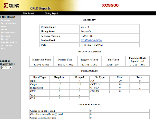
This VHDL circuit design uses 32 macro cells and 27 function blocks.
XC95108 Two-Digit 7-Segment Shift Registers VHDL Example
XC95108 CPLD Reports

I connect the CPLD to its on-board I/O devices (user constraint file) as follow. 

  1. #PACE: Start of Constraints generated by PACE
  2.  
  3. #PACE: Start of PACE I/O Pin Assignments
  4. NET "EN" LOC = "P54" ;
  5. NET "LEDA<0>" LOC = "P23" ;
  6. NET "LEDA<1>" LOC = "P24" ;
  7. NET "LEDA<2>" LOC = "P36" ;
  8. NET "LEDA<3>" LOC = "P34" ;
  9. NET "LEDA<4>" LOC = "P33" ;
  10. NET "LEDA<5>" LOC = "P21" ;
  11. NET "LEDA<6>" LOC = "P35" ;
  12. NET "LEDA<7>" LOC = "P37" ;
  13. NET "LEDB<0>" LOC = "P19" ;
  14. NET "LEDB<1>" LOC = "P20" ;
  15. NET "LEDB<2>" LOC = "P31" ;
  16. NET "LEDB<3>" LOC = "P25" ;
  17. NET "LEDB<4>" LOC = "P26" ;
  18. NET "LEDB<5>" LOC = "P17" ;
  19. NET "LEDB<6>" LOC = "P18" ;
  20. NET "LEDB<7>" LOC = "P32" ;
  21. NET "MISO" LOC = "P53" ;
  22. NET "RST" LOC = "P50" ;
  23. NET "SCK" LOC = "P52" ;
  24.  
  25. #PACE: Start of PACE Area Constraints
  26.  
  27. #PACE: Start of PACE Prohibit Constraints
  28.  
  29. #PACE: End of Constraints generated by PACE
  30.  

Using the Arduino Uno is common for most of electronics hobbyists. I use the Arduino SPI to send 7-Segment data to the XC95108 CPLD Prototype Board. This program will count up and down between 0 and 99.

  1. #include <SPI.h>
  2.  
  3. const char data_7[]={0x3F,0x06,0x5B,0x4F,0x66,0x6D,0x7D,0x07,0x7F,0x6F};
  4. const char EN=10;
  5. volatile char data[2];
  6. volatile char count=0,up_down=0;
  7.  
  8. void setup() {
  9. SPI.begin();
  10. pinMode(EN,OUTPUT);
  11. digitalWrite(EN,LOW);
  12. }
  13.  
  14. void loop() {
  15. data[1]=data_7[count%10];
  16. data[0]=data_7[count/10];
  17. SPI.transfer(data,2);
  18. digitalWrite(EN,HIGH);
  19. delay(1);
  20. digitalWrite(EN,LOW);
  21. if(count==99) up_down=1;
  22. else if(count==0) up_down=0;
  23. if(up_down==1) count--;
  24. else if(up_down==0) count++;
  25. delay(250);
  26. }

The Arduino Uno must connects to the CPLD as follow.

  • Arduino Uno GND              -> XC95108 CPLD GND
  • Arduino Uno SCK (PIN13)   -> XC95108 CPLD (P52)
  • Arduino Uno MOSI (PIN11) -> XC95108 CPLD (P53)
  • Arduino Uno EN (PIN10)     -> XC95108 CPLD (P54)

Click here to download its source file.

XC95108 16-bit Serial In Parallel Out Shift Registers VHDL Example

A Serial-In-Parallel-Out shift register IC is very popular among micro-controller programmers. It's commonly use for I/O extending, LED driving, relay driving, etc. The SN75C595N or the SN74HC164 are commonly used with micro-controllers to expand their outputs.

XC95108 16-bit Serial In Parallel Out Shift Registers VHDL Example
Hardware test on bread-board with Arduino Uno SPI

Using a CPLD/FPGA we can create any digital circuit including this type shift registers chip. In this example, I use the XC95108 CPLD to create a 16-bit serial in parallel out shift registers chip. The chosen language is VHDL.

The designed chip include reset(RST), serial clock(CLK), and serial data in (DIN). Its output is an 16-bit output port connects to LED.

  1. ----------------------------------------------------------------------------------
  2. -- Company:
  3. -- Engineer:
  4. --
  5. -- Create Date: 10:34:09 01/29/2024
  6. -- Design Name:
  7. -- Module Name: shift_regs_16_LED - Behavioral
  8. -- Project Name:
  9. -- Target Devices:
  10. -- Tool versions:
  11. -- Description:
  12. --
  13. -- Dependencies:
  14. --
  15. -- Revision:
  16. -- Revision 0.01 - File Created
  17. -- Additional Comments:
  18. --
  19. ----------------------------------------------------------------------------------
  20. library IEEE;
  21. use IEEE.STD_LOGIC_1164.ALL;
  22.  
  23. -- Uncomment the following library declaration if using
  24. -- arithmetic functions with Signed or Unsigned values
  25. --use IEEE.NUMERIC_STD.ALL;
  26.  
  27. -- Uncomment the following library declaration if instantiating
  28. -- any Xilinx primitives in this code.
  29. --library UNISIM;
  30. --use UNISIM.VComponents.all;
  31.  
  32. entity shift_regs_16_LED is
  33. Port ( CLK : in STD_LOGIC;
  34. RST : in STD_LOGIC;
  35. DIN : in STD_LOGIC;
  36. LEDS : out STD_LOGIC_VECTOR (15 downto 0));
  37. end shift_regs_16_LED;
  38.  
  39. architecture Behavioral of shift_regs_16_LED is
  40. SIGNAL REGS: STD_LOGIC_VECTOR(15 DOWNTO 0);
  41. begin
  42. PROCESS(CLK,RST)
  43. BEGIN
  44. IF(RST='0') THEN REGS<=x"0000";
  45. ELSIF(CLK'EVENT AND CLK='1') THEN
  46. REGS(0)<=DIN;
  47. REGS(1)<=REGS(0);
  48. REGS(2)<=REGS(1);
  49. REGS(3)<=REGS(2);
  50. REGS(4)<=REGS(3);
  51. REGS(5)<=REGS(4);
  52. REGS(6)<=REGS(5);
  53. REGS(7)<=REGS(6);
  54. REGS(8)<=REGS(7);
  55. REGS(9)<=REGS(8);
  56. REGS(10)<=REGS(9);
  57. REGS(11)<=REGS(10);
  58. REGS(12)<=REGS(11);
  59. REGS(13)<=REGS(12);
  60. REGS(14)<=REGS(13);
  61. REGS(15)<=REGS(14);
  62. END IF;
  63. LEDS<=REGS;
  64. END PROCESS;
  65.  
  66. end Behavioral;
  67.  
  68.  

Its internal circuit doesn't need additional clock input to synchronize input data. The data is synchronized with serial clock pin from external device.

Its I/O pins are assigned as follow using the Floorplan I/O tool.

  1. #PACE: Start of Constraints generated by PACE
  2.  
  3. #PACE: Start of PACE I/O Pin Assignments
  4. NET "CLK" LOC = "P48" ;
  5. NET "DIN" LOC = "P50" ;
  6. NET "LEDS<0>" LOC = "P63" ;
  7. NET "LEDS<10>" LOC = "P67" ;
  8. NET "LEDS<11>" LOC = "P68" ;
  9. NET "LEDS<12>" LOC = "P69" ;
  10. NET "LEDS<13>" LOC = "P70" ;
  11. NET "LEDS<14>" LOC = "P71" ;
  12. NET "LEDS<15>" LOC = "P72" ;
  13. NET "LEDS<1>" LOC = "P62" ;
  14. NET "LEDS<2>" LOC = "P61" ;
  15. NET "LEDS<3>" LOC = "P58" ;
  16. NET "LEDS<4>" LOC = "P57" ;
  17. NET "LEDS<5>" LOC = "P56" ;
  18. NET "LEDS<6>" LOC = "P55" ;
  19. NET "LEDS<7>" LOC = "P54" ;
  20. NET "LEDS<8>" LOC = "P65" ;
  21. NET "LEDS<9>" LOC = "P66" ;
  22. NET "RST" LOC = "P47" ;
  23.  
  24. #PACE: Start of PACE Area Constraints
  25.  
  26. #PACE: Start of PACE Prohibit Constraints
  27.  
  28. #PACE: End of Constraints generated by PACE
  29.  

After the design and programming process are completed, we can test this circuit manually with a few on-board input switches. For convenience we can use a popular Arduino Uno as an SPI master device transferring a 16-bit data to this shift registers chip.

  1. #include<SPI.h>
  2.  
  3. void setup() {
  4. SPI.begin();
  5. }
  6.  
  7. char data[2];
  8. void loop() {
  9. data[0]=0xF0;
  10. data[1]=0x0F;
  11. SPI.transfer(data,2);
  12. delay(1000);
  13. data[0]=0x0F;
  14. data[1]=0xF0;
  15. SPI.transfer(data,2);
  16. delay(1000);
  17. }

The circuit connections between the Arduino Uno and the XC95108 CPLD are:

Arduino Uno            XC95108 CPLD Prototype Board

GND                        GND

PIN11 (MOSI)            P50

PIN13 (SCK)               P48

I use the Arduino SPI module and library without bit-banging. Optionally we can use the on-board 7-Segment display instead of the LED.

Click here to download its source file.

Labels

ADC (10) Analog (14) Arduino (12) Atmega16 (19) Audio (2) AVR (20) Charger (1) Cortex-M0 (1) Counter (10) CPLD (25) Digital I/O (22) Display (34) EEPROM (2) Environment Sensor (1) esp8266 (2) Experiment Board (10) I2C (4) Interrupt (7) LCD (1) LDmicro (29) measurement and instrumentation (7) Microchip Studio (3) MikroC (1) One-Shot (3) OpAmp (1) PCB (31) PIC16 Microcontrollers (16) PIC16F877A (2) PIC16F887 MikroC (22) PLC (35) PWM (11) Regulator (1) RTC (2) Sensor (8) Shift Registers (5) SPI (5) Timer (34) UART (2) ultra-sonic sensor (1) USB (1) VHDL (21) xc8 (1) XC95108 (9) XC9536 (15) XC9572 (1) Xilinx (23) Xilinx ISE (22)