In previous post, I use the XC95108 to make a 16-bit LED shift registers. It's similar to the SNHC164 serial in parallel out shift registers chip. Using a CPLD and VHDL code we can customize any digital circuit.
The Arduino Uno and the XC95108 CPLD Prototype Board |
Here I make another serial in parallel out shift registers chip that's similar to the SN74HC595. It's a two-digit 7-Segment display driver with SPI interface. It has the following I/O:
- Reset (RST) input (active low)
- Enable (EN) input for data latching
- Serial Data In (MOSI)
- Serial Clock In (SCK)
- 7-Segment Digit 1 (LEDA)
- and 7-Segment Digit 2 (LEDB).
The 7-Segment display is a two-digit 0.56" red common cathode display. The shift registers process is synchronize with the logic high level of serial clock input (SCK). Shift registers data are latched into the output LED ports at the high to low transition of the EN (Enable) pin.
---------------------------------------------------------------------------------- -- Company: -- Engineer: -- -- Create Date: 08:29:52 01/30/2024 -- Design Name: -- Module Name: spi_7_2 - Behavioral -- Project Name: -- Target Devices: -- Tool versions: -- Description: -- -- Dependencies: -- -- Revision: -- Revision 0.01 - File Created -- Additional Comments: -- ---------------------------------------------------------------------------------- library IEEE; use IEEE.STD_LOGIC_1164.ALL; -- Uncomment the following library declaration if using -- arithmetic functions with Signed or Unsigned values --use IEEE.NUMERIC_STD.ALL; -- Uncomment the following library declaration if instantiating -- any Xilinx primitives in this code. --library UNISIM; --use UNISIM.VComponents.all; entity spi_7_2 is Port ( RST : in STD_LOGIC; EN : in STD_LOGIC; SCK : in STD_LOGIC; MISO : in STD_LOGIC; LEDA : out STD_LOGIC_VECTOR (7 downto 0); LEDB : out STD_LOGIC_VECTOR (7 downto 0)); end spi_7_2; architecture Behavioral of spi_7_2 is SIGNAL REGA,REGB: STD_LOGIC_VECTOR(7 DOWNTO 0); begin PROCESS(SCK,RST,EN) BEGIN IF(RST='0') THEN REGA<=x"00"; REGB<=x"00"; ELSIF(SCK'EVENT AND SCK='1') THEN -- REGISTER A REGA(0)<=MISO; REGA(1)<=REGA(0); REGA(2)<=REGA(1); REGA(3)<=REGA(2); REGA(4)<=REGA(3); REGA(5)<=REGA(4); REGA(6)<=REGA(5); REGA(7)<=REGA(6); -- REGISTER B REGB(0)<=REGA(7); REGB(1)<=REGB(0); REGB(2)<=REGB(1); REGB(3)<=REGB(2); REGB(4)<=REGB(3); REGB(5)<=REGB(4); REGB(6)<=REGB(5); REGB(7)<=REGB(6); END IF; -- INPUT DATA LATCH IF(EN'EVENT AND EN='1') THEN LEDA<=REGA; LEDB<=REGB; END IF; END PROCESS; end Behavioral;
This VHDL circuit design uses 32 macro cells and 27 function blocks.
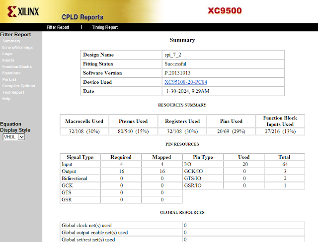
XC95108 CPLD Reports |
I connect the CPLD to its on-board I/O devices (user constraint file) as follow.
#PACE: Start of Constraints generated by PACE #PACE: Start of PACE I/O Pin Assignments NET "EN" LOC = "P54" ; NET "LEDA<0>" LOC = "P23" ; NET "LEDA<1>" LOC = "P24" ; NET "LEDA<2>" LOC = "P36" ; NET "LEDA<3>" LOC = "P34" ; NET "LEDA<4>" LOC = "P33" ; NET "LEDA<5>" LOC = "P21" ; NET "LEDA<6>" LOC = "P35" ; NET "LEDA<7>" LOC = "P37" ; NET "LEDB<0>" LOC = "P19" ; NET "LEDB<1>" LOC = "P20" ; NET "LEDB<2>" LOC = "P31" ; NET "LEDB<3>" LOC = "P25" ; NET "LEDB<4>" LOC = "P26" ; NET "LEDB<5>" LOC = "P17" ; NET "LEDB<6>" LOC = "P18" ; NET "LEDB<7>" LOC = "P32" ; NET "MISO" LOC = "P53" ; NET "RST" LOC = "P50" ; NET "SCK" LOC = "P52" ; #PACE: Start of PACE Area Constraints #PACE: Start of PACE Prohibit Constraints #PACE: End of Constraints generated by PACE
Using the Arduino Uno is common for most of electronics hobbyists. I use the Arduino SPI to send 7-Segment data to the XC95108 CPLD Prototype Board. This program will count up and down between 0 and 99.
#include <SPI.h> const char data_7[]={0x3F,0x06,0x5B,0x4F,0x66,0x6D,0x7D,0x07,0x7F,0x6F}; const char EN=10; volatile char data[2]; volatile char count=0,up_down=0; void setup() { SPI.begin(); pinMode(EN,OUTPUT); digitalWrite(EN,LOW); } void loop() { data[1]=data_7[count%10]; data[0]=data_7[count/10]; SPI.transfer(data,2); digitalWrite(EN,HIGH); delay(1); digitalWrite(EN,LOW); if(count==99) up_down=1; else if(count==0) up_down=0; if(up_down==1) count--; else if(up_down==0) count++; delay(250); }
The Arduino Uno must connects to the CPLD as follow.
- Arduino Uno GND -> XC95108 CPLD GND
- Arduino Uno SCK (PIN13) -> XC95108 CPLD (P52)
- Arduino Uno MOSI (PIN11) -> XC95108 CPLD (P53)
- Arduino Uno EN (PIN10) -> XC95108 CPLD (P54)
Click here to download its source file.
No comments:
Post a Comment