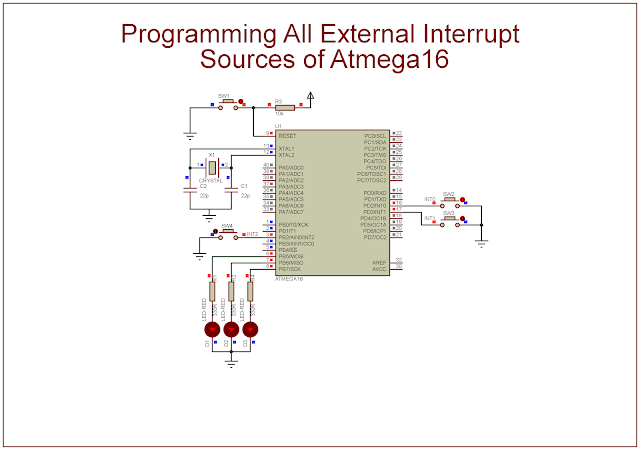
In previous post, I show a simple programming example of INT0. As it's already stated, the Atmega16 has up to 3 external interrupt sources. In this example, I use all its external interrupt sources, the INT0, the INT1, and the INT2.
I select the low logic level of these interrupt source to trigger the ISR. Whenever any interrupt occurs, its corresponding output LEDs will toggle its logic state. The output LEDs are PB5, PB6, and PB7.
 |
| Program simulation |
Source Code:
1 2 3 4 5 6 7 8 9 10 11 12 13 14 15 16 17 18 19 20 21 22 23 24 25 26 27 28 29 30 31 32 33 34 35 36 37 38 39 40 41 42 43 44 45 46 47 48 49 50 51 52 | /* * atmega16AllExtIntEx.c * * Created: 6/10/2022 7:06:23 PM * Author : Admin */ #include <avr/io.h> #include <avr/interrupt.h> int main(void) { //PD2 and PD3 Input DDRD&=~(1<<2); DDRD&=~(1<<3); //Turn on PD2 and PD3 high PORTD|=(1<<2)|(1<<3); //PortB output DDRB=0xFF; //PB2 input DDRB&=~(1<<2); //Turn PB2 high PORTB|=(1<<2); //Enable INT0...2 request GICR|=(1<<INT0)|(1<<INT1)|(1<<INT2); //Enable interrupt sei(); //Clear Flag GIFR|=(1<<INTF0); while (1) { } return 0; } //Interrupt Service Routine - ISR ISR(INT0_vect){ //Toggle RB5 PORTB^=0x20; } ISR(INT1_vect){ //Toggle RB6 PORTB^=0x40; } ISR(INT2_vect){ //Toggle RB7 PORTB^=0x80; } |
Click here to download its zip file.
No comments:
Post a Comment