 |
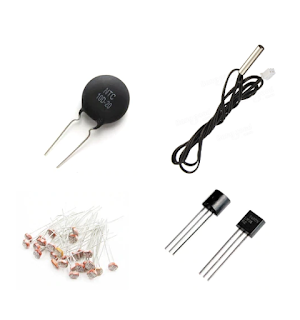
| Analog Output Sensors |
To read the value from these sensor, the PLC need to command to its analog reading instruction. The A/D converter read instruction is a unique ladder diagram instruction that accomplish the analog input reading using only PLC cycle time.
 |
| A/D Converter Read Instruction Symbol |
It's configured as follow.
 |
| A/D converter Read instruction property |
Without any optional settings, the A/D uses a single-end reading mode. The references voltage is internally wired to GND and VDD of the target MCU - for example PIC16F876. For other MCU such as AVR, it's convenient to check the device datasheet and the user's manual of this ladder diagram IDE.
PIC16F876 comes with a 10-bit A/D converter module. It gives a 10-bit resolutions, creates a digital value of 1024 (0 to 1023).
An introductory example show how to use this instruction to read an analog input fed to RA0. The PLC convert the analog input value to digital value before it sends to the host PC via UART terminal. This task is accomplished using a rung of ladder diagram instructions. This rung is activated for every 400 mS, powered by a cyclic on/off timer instruction.
 |
| A/D converter read ladder diagram example |
The selected processor of this PLC is PIC16F876, clocks to maximum frequency at 20 MHz. The PLC UART baud rate is 9600 by default due a minimum system requirements.
 |
| Schematic Diagram |
Click here to download the zip file of this ladder diagram example.
No comments:
Post a Comment