Introduction
We have driven a long journey on Timer/Counter0 module of ATMega16. Finally, we will discuss about this module to operate in counter mode. Here we will talk briefly about a counter with some different techniques of making it up.
Standard Logic Counter IC
Typically a digital counter IC made up of flip-flops, accepting a digital pulse input. Its internal flip-flips continuous to change whenever it has incoming input pulse. This IC has many kind of output – a binary output, a Binary Coded Decimal (BCD) output, etc. For example a 7490 decade counter.
Counter in Microcontroller
A digital logic IC counter-like system can be created using an 8-bit microcontroller. The easiest way to make it is coding a microcontroller in Assembly or C language to count an external pulse straightly. This method is not accurate nor responsive, since it has some problems of noisy input created by bounced switching.
Another way is to use Timer/Counter module inside a microcontroller since it can count in two ways – internal and external. An external counting refers to counting an outside world input pulse fed to its corresponding input counting pin, as an example of the Timer/Counter0 module of ATMega16.
Using this module to make a digital counter is very effective in coding since it requires a few lines of code that configure the microcontroller counting peripheral. It’s fast and responsive. The input pulse frequency is more than 50MHz.
AVR GCC to Program Timer/Counter0 in Counter Mode
We have shown a lot about the details of Timer/Counter0 peripheral of ATMega16 that we will not show it more here. However putting the controller to operate in counter mode is done with a few lines of C code with some optional port setting.
Register Setting
Making this counter to run require only one register – the Timer/Counter Control Register (TCNT0). Its external input clock (pulse) have two transition – rising and falling edge. These two transition can be selected in Clock Select bit of TCNT0.
 |
| Clock Select bit of Timer/Counter Control Register |
Setting CS02:00 to 0x06, the counter increase its content whenever the external clock source on T0 (PB0) change from high to low (falling edge). For a falling edge (low to high transition) we must set CS02:00 to 0x07 to increase the content of counter.
T0 is Timer/Counter0 counter input pin locates at PB0 of Port B. In counter mode we no need to configure this pin to input, as it’s automatically set.
Similarly to timer mode, Timer/Counter Register (TCNT0) store the counting result. This 8-bit register overflows after it reaches 0xFF and rolls back to 0x00. The TOV0 flag is set at this point.
A Program to Count a Rising Edge Pulse
Conventionally an external clock source is active at its rising edge (low to high). So here we will use this microcontroller internal counter to work in this way.
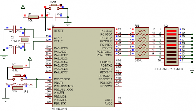
This introductory example, counts a low-to-high external pulse. A binary representation output of the 8-bit TCNT0 will display on Port C. Clock Selection bit CS02:00 set to 0x07 in hexadecimal. T0 (PB0) external clock input pin is no need to set to a digital input direction in counter mode.
There are no appropriate port pin selection on my AVR development board. So I decide to test this program in software simulator – Proteus.
 |
| Proteus simulator program testing |
The core coding of counter consists of a few lines of code.
We can detect the rising edge of input pulse requires two external resistors.
A Program to Count a Falling Edge Pulse
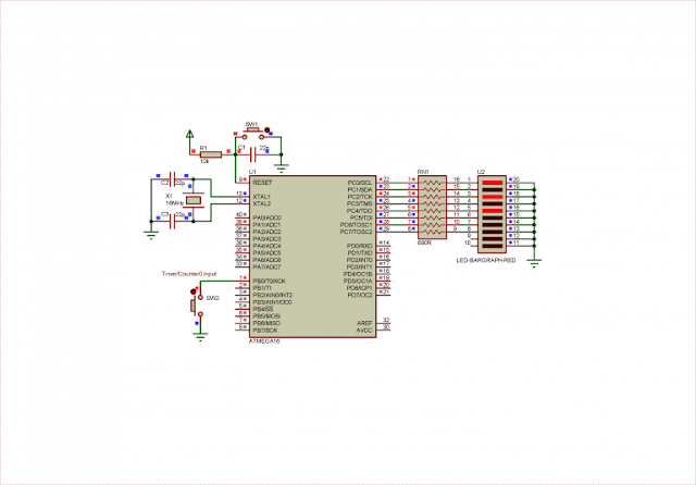
Optionally we can detecting the present of input pulse on its falling edge. AVR GCC source code remain the same but it excepts the transition setting in Clock Select bit of TCCR0. Again the schematic diagram and program testing is done in Proteus simulator.
 |
| Program testing in Proteus simulator |

No comments:
Post a Comment