Introduction
Pulse Width Modulation (PWM) generate an analog output waveform from microcontroller output pin. Enhanced Capture/Compare/PWM (CCP1) peripheral of PIC16F887 is able to generate analog output signal.
 |
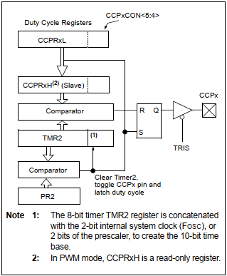
| Block diagram of PWM module of CCP1 |
MikroC PWM Library
PWM library could be found in Hardware Library of MikroC compiler for PIC. There are four function in this library to access PWM module.
1- void PWMx_Init(long freq);
This function initializes PWM module with 0% duty cycle. The frequency parameter "freq" is specified in Hz. This function returns nothing. For example,
PWM1_Init(5000);
which initialize PWM of CCP1 module with a frequency of 5kHz.
2- void PWMx_Set_Duty(unsigned short duty_ratio);
Set any PWM module duty cycle. Parameter duty_ratio varies between 0 and 255. Actual duty cycle of PWM output is in % which is
(Percent*255)/100 (in %).
This function returns nothing.
3- void PWMx_Start(void);
This function starts PWM waveform generation. For example,
PWM1_Start();
generates output PWM waveform on its corresponding pin.
4- void PWMx_Stop(void);
This functions stop PWM output generation, for example, PWM1_Stop(); .
We will discuss about the details of PWM peripheral here. We will use this library functions to program PWM of PIC16F887.
PWM Programming in MikroC
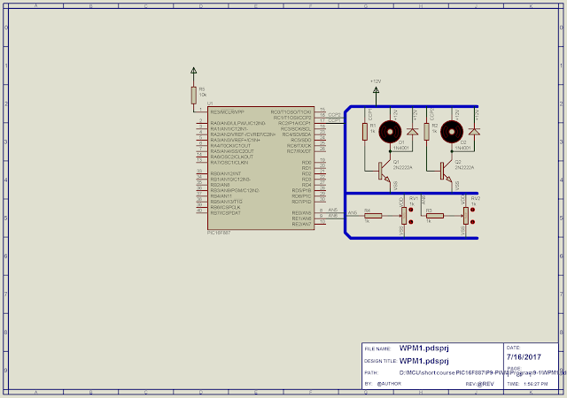
In this introductory programming example, we will use two analog input channels to adjust two PWM outputs via CCP1 and CCP2. Two variable resistors connect to AN5 and AN6 vary input analog values.
 |
| Schematic diagram |
Two DC motors connect to CCP1 and CCP2 output of PIC16F887, driven by their corresponding transistors. Output frequency of these two PWM output are fixed of 5kHz. Their output speeds vary by variation of PWM duty cycle.
MikroC program of this example is shown below.
Click here to download this example package.
No comments:
Post a Comment