Introduction
We have discussed about interrupt-on-change of Port B in PIC16F887 microcontroller in previous post. Programming and prototyping were done using MikroC and Proteus VSM.
Using interrupt the program and hardware operate in a very responsive manner. Main program keeps executing its major tasks. In this example we will use the features of Port B interrupt-on-change to increase, decrease, start, and stop a DC motor drive.
Pulse Width Modulation (PWM) of a microcontroller is usually need in DC motor driving. However within this introductory PIC tutorial we will not drive deeper into PWM module of PIC16F887. PIC C program will be written to implement a software delay library in MikroC to produce a variable PWM signal with a specific frequency and adjustable duty cycle.
This is just a software emulation of PWM. Using this technique we can create a lower frequency of signal. It's not robust and advance like using a hardware PWM module of PIC microcontroller.
Circuit Design
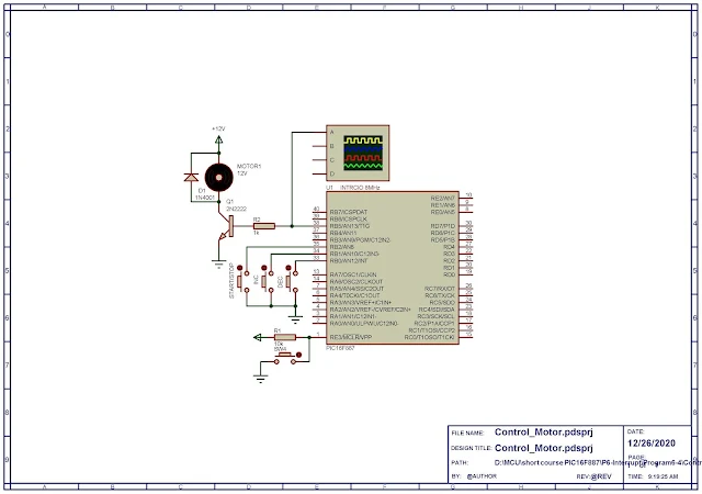
Circuit diagram design and testing of embedded controller program are tested using Proteus VSM simulator. At my workshop I don't have any laboratory equipment like oscilloscope or function generator. It's enough to run this microcontroller in simulator.
 |
| Schematic Diagram designed in Proteus simulator |
Microcontroller use its internal maximum 8MHz oscillator. Three push buttons connect to RB5, RB6, and RB7 control the rotation of DC motor. They are interrupt driven. DC motor is assumed to work in +12V with an additional transistor driver.
Programming in MikroC
C program configures the controller to access its internal 8MHz oscillator. Port B interrupt-on-change occurs at the low logic level of Port B input, as any button is being pressed. RB3 generates an software PWM to drive its output DC motor.
Since there's no hardware PWM module used in this example we use Vdelay_ms to create ON and OFF delay time. These delay times vary the output duty cycle of software PWM waveform.
void Vdelay_ms(unsigned time_in_ms);
This MikroC function creates a software delay in duration of variable time_in_ms milliseconds.
Simulation of Program
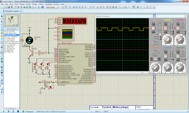
Proteus VSM simulator works well for this embedded controller program.
 |
| Program simulation in Proteus |
Output software PWM waveform has a frequency of 50Hz measured by virtual frequency meter. Click here to download this example in zip file package.
No comments:
Post a Comment