Thursday, October 8, 2020

Using PORTA of PIC16F887 as a digital I/O

An Overview Of PORTA

Some pins PORTA of the PIC16F887 is multiplexed with the analog input channels. Using them as an input they are the analog input channel by default.

PORTA  is the input output read/write register.


It's data direction is controlled by TRISA. Setting TRISA to output the data to outside world otherwise accepting the data into the MCU.


The ANSEL register is set by default, keeping PORTA input as an analog input channel. Clearing some bits of this register to get back to the digital input pin.

MikroC Programming of PORTA


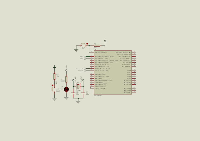
All the registers discussed above are available in MikroC with its own label - for example the ANSEL. I program the controller to read a digital input data from RA0 - AN0 is ignored. This digital input bit will be display on RA1, connects to an output LED circuit.
Using PORTA of PIC16F887 as a digital I/O
Schematic Diagram

When this prototyping circuit installed in the physical board, do not forget to wire the supply pins. The circuit works at 5 V DC. The CPU clocks at 20 MHz.

No comments:

Post a Comment

Labels

ADC (10) Analog (14) Arduino (12) Atmega16 (19) Audio (2) AVR (20) Charger (1) Cortex-M0 (1) Counter (10) CPLD (25) Digital I/O (22) Display (34) EEPROM (2) Environment Sensor (1) esp8266 (2) Experiment Board (10) I2C (4) Interrupt (7) LCD (1) LDmicro (29) measurement and instrumentation (7) Microchip Studio (3) MikroC (1) One-Shot (3) OpAmp (1) PCB (31) PIC16 Microcontrollers (16) PIC16F877A (2) PIC16F887 MikroC (22) PLC (35) PWM (11) Regulator (1) RTC (2) Sensor (8) Shift Registers (5) SPI (5) Timer (34) UART (2) ultra-sonic sensor (1) USB (1) VHDL (21) xc8 (1) XC95108 (9) XC9536 (15) XC9572 (1) Xilinx (23) Xilinx ISE (22)