Overview Of The Internal Oscillator of PIC16F887
One of the extended features of PIC16F887 over the previous PIC16F887A is the internal calibrated RC oscillator. Using this internal oscillator, the clocking module inside works statically, mostly prevented from the noisy environment creates by the external RF signal.
Furthermore, there're many options with internal clock. The external clock pins - RA6 and RA7 could be selected as a digital input output pin when the MCU clock is configured as internal oscillator with digital I/O.
The internal oscillator is divided into two blocks - LFINTOSC and HFINTOSC. The LFINTOSC in a lower frequency clock below 31 kHz. The HFINTOSC is a higher frequency ranges from 125 kHz to 8 MHz.
The internal clock setup must be done in the configuration bits and the OSCCON register. Another register OSCTUNE give a steady tuning to any frequency while the program is running, without any interruption.
 |
| PIC MCU clock source block diagram |
In MikroC the configuration of the MCU must be done in the MCU property window. In this IDE press Shift + Ctrl + E to get this window.
The OSCTUNE (Oscillator Tuning Register)
The OSCCON (Oscillator Controller Register)
Programming in MikroC
 |
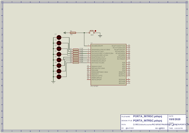
| Schematic Diagram |
The C source code in MikroC setup the internal oscillator one-by-on.


Thank you
ReplyDeleteYou're Welcome.
Delete