Thursday, September 24, 2020

PLC turn-on delay Tdon ladder diagram instruction

This instruction is a type of PLC delay timer. The timer on delay Tdon instruction keeps track of its input high time but it's not store the timing value like the retentive timer.
Tdon instruction symbol

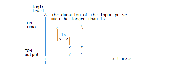
If the input high time into this instruction is greater than the preset delay time, it will output true. And it will change to false at the moment the input falls to low.
PLC turn-on delay Tdon ladder diagram instruction
Tdon timing diagram. The input delay time of one second is set in the
instruction property.

The delay time may be preset in its property.

PLC turn-on delay Tdon ladder diagram instruction
Tdon instruction property. The picture above I set the delay time to 5000 mS or five seconds.

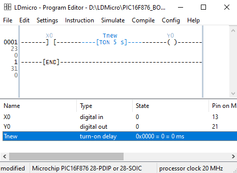
A very simple and easy ladder diagram example show a single rung of the program that made of an input contact, a Tdon instruction and an output coil.


PLC turn-on delay Tdon ladder diagram instruction
Ladder diagram example program

It's not necessary to draw and simulate the ladder diagram in any EDA software. But I wish you can make it as leisure. 


PLC turn-on delay Tdon ladder diagram instruction
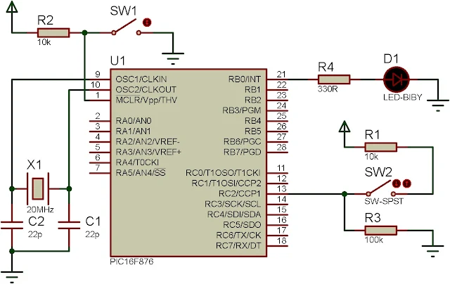
Schematic Diagram

Click here to download the zip file of this working example.


No comments:

Post a Comment

Labels

ADC (10) Analog (14) Arduino (12) Atmega16 (19) Audio (2) AVR (20) Charger (1) Cortex-M0 (1) Counter (10) CPLD (25) Digital I/O (22) Display (34) EEPROM (2) Environment Sensor (1) esp8266 (2) Experiment Board (10) I2C (4) Interrupt (7) LCD (1) LDmicro (29) measurement and instrumentation (7) Microchip Studio (3) MikroC (1) One-Shot (3) OpAmp (1) PCB (31) PIC16 Microcontrollers (16) PIC16F877A (2) PIC16F887 MikroC (22) PLC (35) PWM (11) Regulator (1) RTC (2) Sensor (8) Shift Registers (5) SPI (5) Timer (34) UART (2) ultra-sonic sensor (1) USB (1) VHDL (21) xc8 (1) XC95108 (9) XC9536 (15) XC9572 (1) Xilinx (23) Xilinx ISE (22)