Monday, September 21, 2020

PLC shift register ladder diagram instruction

Just like a shift register in digital electronics, the PLC shift register contains a number of register. Each register is 16-bit wise. The content of each register shifts from one stage to next stage, for example reg[2]=reg[1] and reg[1]=reg[0].
Shift Register Instruction Symbol


We must name the register and its stage.

Instruction Property

Stages define the number of the 16-bit shift register in used.

In this example, I use a UART terminal of a host PC to send the character to the PLC and echo the character back.
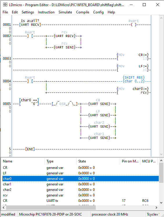


PLC shift register ladder diagram instruction
Ladder Diagram Example

PLC shift register ladder diagram instruction
Schematic Diagram


Click here to download this ladder diagram example.


No comments:

Post a Comment

Labels

ADC (10) Analog (14) Arduino (12) Atmega16 (19) Audio (2) AVR (20) Charger (1) Cortex-M0 (1) Counter (10) CPLD (25) Digital I/O (22) Display (34) EEPROM (2) Environment Sensor (1) esp8266 (2) Experiment Board (10) I2C (4) Interrupt (7) LCD (1) LDmicro (29) measurement and instrumentation (7) Microchip Studio (3) MikroC (1) One-Shot (3) OpAmp (1) PCB (31) PIC16 Microcontrollers (16) PIC16F877A (2) PIC16F887 MikroC (22) PLC (35) PWM (11) Regulator (1) RTC (2) Sensor (8) Shift Registers (5) SPI (5) Timer (34) UART (2) ultra-sonic sensor (1) USB (1) VHDL (21) xc8 (1) XC95108 (9) XC9536 (15) XC9572 (1) Xilinx (23) Xilinx ISE (22)