Requirements For PCB Making Using Dry Film Technique
Creating a printed circuit board (PCB) with dry film method, could produce a high quality PCB. It's because of good copper track coating. Comparing to a simple toner transfer method, it's excellent in output but it costs more dollars and more time consuming.
 |
| A sample a pre-fabricated PCB made by a Gerber viewer |
The dry film is made from polymer. it is photo sensitive to UV light. In industrial PCB making, dry film is choice of PCB copper tracking protecting. In the market it cost around 10 US Dollars for 30 cm by 5 meters.
 |
| My dry film in use. It is 5 meters long. I bought it from E bay for 8 US Dollars. |
However using dry film for PCB making requires UV lamp with a precise timer to make the process more accurate. A low lost timer made by some Chinese manufacturer cost around 3 US Dollars.
The source of UV light beside the sun light are a UV light bulb or a popular UV LED available on line.
 |
| A low cost Chinese light bulb works at 220V AC with the output power of 40 W. It's suitable for personal use. I use this device for my electronic workshop at home. |
 |
| A sample PCB I made using dry film method with solder mask coating in 2008. |
Making A DIY UV Time Exposes Unit Using PIC16F876A
Design Requirements
For a normal control device, it require some user inputs, a display output and a driving output.
User input has no other words than a push button in common.
A display device, could be a simple seven-segment display because it has a big display value and very simple to program.
An output driving, commonly drive an AC load. In this project, it drive an output relay to switch the AC UV light bulb on and off.
To make an embedded controller project, we must thing about all controller's resource requirement that fit the project. For this simple project, an 8-bit PIC device is a good choice. Most 8-bit PIC has a rich of digital input output, analog inputs and PWM output driving.
I posses a lot of PIC16F876A I bought for my working project to some companies. I have left a dozen of it from the finished projects.
 |
| A reference image of this device taken from RS components. Some components I possess are very old and used that is not suitable to post them here. |
The Completed Project
In this design, I use the following stuffs to make a timer work well for my personal use:
- A variable resistor used for adjust time
- An ENTER button used for inputting the time value
- A LOAD button used for reading the saved timing from previous setting
- An 8-digit multiplexed displays for display the time
- An output relay driver to switch the lamp on and off
- A buzzer alert the beginning and the end of the running timer
 |
| The picture of the completed project |
The display digit are 0.36 inches diagonal. Conventionally, the multiplexing method could work well for only 8 digits.
 |
| Schematic Diagram I designed in Proteus 8 |
 |
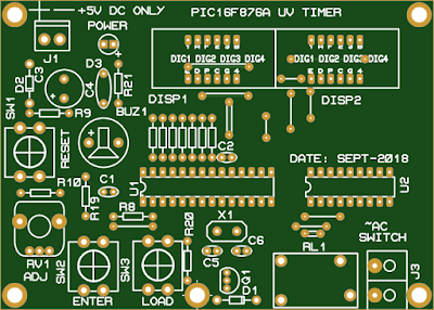
| A sample PCB design the red line indicates the design rule error, but it doesn't matter. |
 |
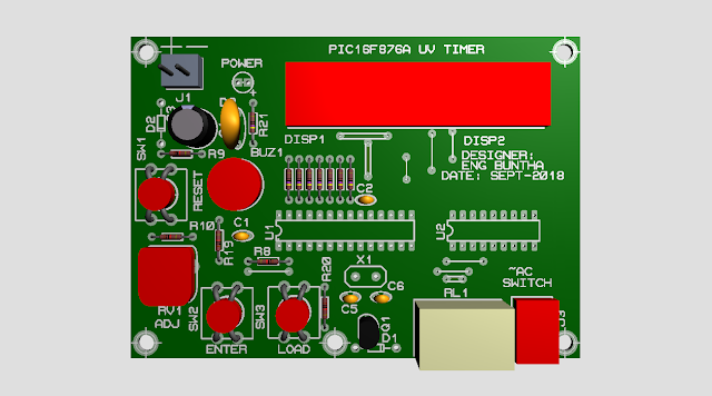
| A computer software rendered of this design |
I took the photo of my finished work as below.
MPLABX XC8 Source Code
The overall program is written using XC8 from the device vendor.
The config.h file lists below.
The completed project archive could be downloaded here.
I shared this project on the PCB fab service website.

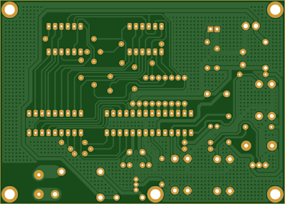
The pictures below show a sample pre-production PCB created by the Gerber viewer.
 |
| Components Side |
 |
| Copper Soldering Side |


No comments:
Post a Comment