Friday, August 13, 2021

ICSP Board for 8-bit PIC Microcontroller


Introduction

A device programmer is needed at the time of physical hardware prototyping. Popular PIC microcontroller programmer is a low cost PICKIT2 programmer/debugger. 


A 3D Sample of This design

Typically a microcontroller must be burned using a programmer before it’s placed on breadboard. Hence we need a In-Circuit Serial Programming (ICSP) adapter board for safety and time saving intention. 

ICSP Board for 8-bit PIC Microcontroller
Breadboard prototyping

The picture above is a PIC16F818 physical hardware prototyping on breadboard. I needed to program PIC16F818 using an ICSP board before this circuit is assembled on breadboard.

Schematic and PCB Design

I designed and fabricated this printed circuit project by myself. Both schematic and Printed Circuit Board (PCB) design was done using Proteus VSM version 8.

Schematic

Schematic design for this PCB made of a little counts of component. There are two Universal ZIF socket to fit any PIC microcontroller with more than 14 pin counts. Another 8-pin IC socket is placed to fit any 8-pin PIC microcontroller. A six-pin ICSP header is a connection between this board and PICKIT2 device programmer. However this header contain only five active signal of its six signals.


ICSP Board for 8-bit PIC Microcontroller
Schematic diagram for PICKIT2 ICSP Adapter

I used two-row connector to denote IC sockets in schematic.

PCB Design

Schematic and PCB design tools are integrated in one IDE of Proteus VSM 8. I placed and routed all on-board components as follow.

ICSP Board for 8-bit PIC Microcontroller
Board view of this design

It seems to exist two layer of copper track of this PCB. However the top (red) track can be replace by wire jumpers, making it to become a single sided PCB.

ICSP Board for 8-bit PIC Microcontroller
3D View of This Design

We can fabricate this printed circuit using a simple toner-transfer-method by hand.


ICSP Board for 8-bit PIC Microcontroller
Top Copper Layer


ICSP Board for 8-bit PIC Microcontroller
Components (Silk Screen) Layer

ICSP Board for 8-bit PIC Microcontroller
Bottom Copper Layer

Circuit Board Fabrication

Now it’s a few years that I fabricated this PCB by hands. Circuit board was made by toner-transfer-method. Bottom copper side and top silk of component legend was made by photo-resist solder mask.

ICSP Board for 8-bit PIC Microcontroller
Copper soldering side of this PCB


Top layer consisted of some old components that I could not show them here.


Result

I have been using this adapter a few years now. It fits most of 8-bit PIC micro-devices. Programmer software I have been using is a DIY PICKIT2 programmer/debugger in clone version I made.
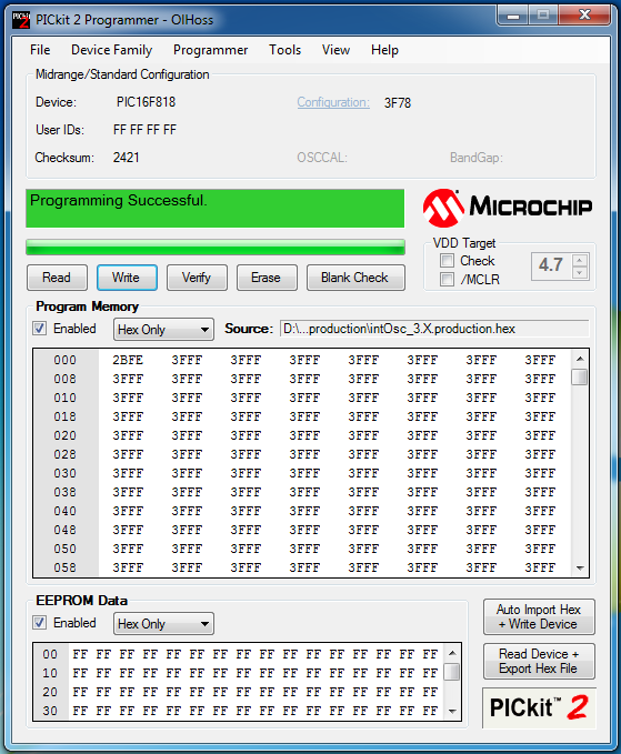
ICSP Board for 8-bit PIC Microcontroller
PICKIT2 device ICSP programming for this adapter

I have tested this adapter with all of PICMicro devices I have in stock.

  • 40-pin devices: PIC18F4550, PIC18F452, PIC18F4431, PIC16F887, PIC16F917, PIC16F877A, etc.
  • 28-pin device: PIC18F2550, PIC16F886, PIC16F876A, etc.
  • 18-pin devices: PIC18F1220, PIC16F1827, PIC16F716, PIC16F628A, PIC16F818/819, PIC16F84A, etc.
  • 8-pin devices: PIC12F629, PIC12F675, PIC12F615, PIC12F635, etc.

I hope it works for all 8-bit PIC micro controllers in DIP package.


Sunday, August 8, 2021

ATMega16 Interfaces To A Discrete 7-Segments Display


Overview

A 7-Segments display commonly found in a typical digital electronics equipment, a temperature controlled switch, a sign board, etc.

It made of segment-shaped of LED with seven light emitting diodes to creates a pattern of numbers, sign, or any characters with an optional dotting point (dp).

ATMega16 Interfaces To A Discrete 7-Segments Display
Some common anode 7-segments display type with the size of one inch. I use these stuffs for my serial display board.

Technical Data

A 7-Segments display varies in its display size, color and its common configurations. I have seen some available sizes of this type of display, 0.36″, 0.40″, 0.56″, 1″, 2.3″, 3″, 4″ and 5″.

Some Parameters

The size refers to the effective display size. Red in output color is a preferred one’s for most hobbyists. The common configuration are the Common Anode (CA) and the Common Cathode (CC). The designer may select between this two kind of configuration to work with the output of any digital IC or embedded controller.

ATMega16 Interfaces To A Discrete 7-Segments Display
The mechanical diagram and the internal circuit arrangement of a single one inch 7-Segments display.

Some hobbyists make this display by connecting multiple LED to make the segments and dotting point.

Each segment of this one inch size display typically supplied at 3.4V for the 20mA forward current. Some large display size above 2.3 inches have a typical forward current of 25mA with the nominal forward voltage of 9.25V.

Display Representation

A parallel output port of a digital IC or a microcontroller output data to this display. It’s 8-bit including the dotting point. However the dotting point is optional, and it usually bit-wise ORed within the output port.

Typically the programmer maps the segments to a corresponding value in a table. For the common anode display, we have a table below.


DisplaygfedcbaHEX
0OFFONONONONONON0xC0
1OFFOFFOFFOFFONONOFF0xF9
2ONOFFONONOFFONON0xA4
3ONOFFOFFONONONON0xB0
4ONONOFFOFFONONOFF0x99
5ONONOFFONONOFFON0x92
6ONONONONONOFFON0x82
7OFFOFFOFFOFFONONON0xF8
8ONONONONONONON0x80
9ONONOFFONONONON0x90
A minimum common anode type 7-Segments Data Table of decimal numbers between 0 and 9

For a common cathode type display, the 7-Segments data table lists below.

DisplaygfedcbaHEX
0OFFONONONONONON0x3F
1OFFOFFOFFOFFONONOFF0x06
2ONOFFONONOFFONON0x5B
3ONOFFOFFONONONON0x4F
4ONONOFFOFFONONOFF0x66
5ONONOFFONONOFFON0x6D
6ONONONONONOFFON0x7D
7OFFOFFOFFOFFONONON0x07
8ONONONONONONON0x7F
9ONONOFFONONONON0x6F
A minimum common cathode type 7-Segments Data Table of decimal numbers between 0 and 9

It’s not only decimal numbers, we can create some ASCII characters to show on this display – for example A, B, L, etc. Due to a limited content I don’t list them all here. We will see them in the programming section.

Interfacing And Programming

A parallel port output of a digital IC or a microcontroller/microprocessor connects to this display via current limiting resistors. These resistors divide the voltage between the LED segment to around 3.4V (1 inches size display), to get a nominal forward current 20mA.

Here I preferred a one inch common anode red display, I stock in my warehouse.

ATMega16 Interfaces To A Discrete 7-Segments Display
A single red common anode 7-Segments display – 7SR10012BS I stock.


Microcontroller To 7-Segments Interface

Port C of ATMega16 outputs 7-Segments data to this display via current limiting resistors. With a nominal forward current of 20mA, the voltage drop at each segment is 3.7V. We need to find the an appropriate value of resistor. The onboard devices including the ATMega16 supplies at 5V. So Port C digital output high to external devices must be 5V. Using the voltage divider rule, current limiting resistor is 63 Ohm. However, I only have a 68 Ohm one’s in my stock.

ATMega16 Interfaces To A Discrete 7-Segments Display

Schematic Diagram Of This Example

Atmel Studio 7 C Programming

Using C in Atmel Studio, we don’t need any hardware library to code within this simple example. It’s nothing more than a digital I/O programming. One important note is creating a 7-Segments data table that have shown in the table above.

Here we use a common anode type display. The display will show a decimal number from 0 to 9 and a character from A to F. The program just display the counting value from 0 to 15, then roll back to 0 and vice versa.

  1. /*
  2.  * discreteSsdCa.c
  3.  *
  4.  * Created: 11/14/2020 6:46:30 PM
  5.  * Author : Admin
  6.  */
  7.  
  8. #include <avr/io.h>
  9.  
  10. #define F_CPU 16000000UL
  11. #include <util/delay.h>
  12.  
  13. int main(void)
  14. {
  15. //7-Segment data table
  16. unsigned char cAnode[16]={0xC0,0xF9,0xA4,0xB0,0x99,0x92,0x82,0xF8,0x80,0x90,0x88,
  17. 0x83,0xC6,0xA1,0x86,0x8E};
  18. //counting parameter
  19. unsigned char cnt=0;
  20. //Port C As Output
  21. DDRC=0xFF;
  22. while (1)
  23. {
  24. //Display the 7-Segments Data
  25. PORTC=cAnode[cnt];
  26. //Increase the counter
  27. cnt++;
  28. //Reset when it reaches 16
  29. if(cnt>15) cnt=0;
  30. _delay_ms(1000);
  31. }
  32. }


On my development board I externally add a one inch 7-Segments display inserted on a bread board.


ATMega16 Interfaces To A Discrete 7-Segments Display
A program test using development board with some external add-on components.

 Click here to download a zip file of this programming example. Let see this video on YouTube.


Sunday, August 1, 2021

ATMega16 Digital Port Reading And Writing


Digital I/O

The ATMega16 AVR has up to four digital Input/Output ports. Those ports are bidirectional read/write port.

ATMega16 Digital Port Reading And Writing
ATMega16 40-pin DIP pin diagram

These four digital I/O ports are,

  • Port A – PA
  • Port B – PB
  • Port C – PC
  • Port D – PD

Each port is 8-bit wide. Beside the digital I/O function, these ports have other purposes,

  • external interrupt
  • counter inputs
  • PWM outputs
  • SPI/TWI communication
  • USART communication
  • Analog inputs, etc.

PORT Register And Direction Control

Output Direction

Each port is configurable as a digital input, or a digital output. The PORTx is an output register. To configure the any port as an output port, its corresponding data direction register, DDRx register must set.

As an instance, the programmer needs PA to output its digital data. The assignment in a C code must be set as follow,

DDRA=0xFF;   //PORTA is a fully output port
PORTA=0xAA;  //Output the hex value AA from PORTA

Let see another example, the lower nibble of PB is the output.

DDRB=0x0F;   //PORTB3.0 are the outputs
PORTB=0x02   //Set the output bit 1 of PORTB

Input Direction

A DDRx register must be cleared to configure the corresponding port as a digital input. PINx is its corresponding input buffer. Reading from the PINx register to get the logic state of the digital inputs.


For example, all bits of PA are the digital input.

DDRA=0x00;     //Configure PA as digital input
myState=PINA;  //Read the digital input logic state from PA

As in this instance, the lower nibble of PB is a digital input part.

DDRB=0xF0;         //PB3.0 are the digital input bits
myState=0x0F&PINB  //Read the digital input at the lower nibble

Digital Port Internal Weak Pull Up Resistors

For most of PIC microcontroller users, they usually think about the PORTB internal weak input pull up resistor. However, in the ATMega16 microcontroller every ports have their own internal weak pull up resistors. Each weak pull up resistor of one port is individually configurable.

This feature is commonly used in the input direction. To turn on the internal weak pull up resistors,

  • Set the data direction to the input
  • Write a preferred value to the PORTx register

For example, a lower nibble of PD is a digital input. The programmer turn on the internal weak pull up resistor of this lower nibble.

DDRD=0xF0;   //PIND3.0 are the digital inputs
PORTD=0x0F;  //Turn on the weak pull up resistors of the PINC3.0

Atmel Studio 7 C Programming

Overview

Within this introductory example, I select port A as a digital input port. PB is configured as a digital output port. The main program loop reads the digital data from PINA, while port b output this digital data. We don’t need to add any external resistors to the digital input pins since the programmer just need to write 0xFF to PORTA.


We need to know about port A register associations.

ATMega16 Digital Port Reading And Writing
Port A Data Register – PORTA

ATMega16 Digital Port Reading And Writing
Port A Data Direction Register – DDRA

ATMega16 Digital Port Reading And Writing
Port A Inputs Pin Address – PINA


Finally, the registers associate to port B list below.

ATMega16 Digital Port Reading And Writing
Port B Data Register – PORTB

 
ATMega16 Digital Port Reading And Writing
Port B Data Direction Register – DDRB

Schematic Diagram

I draw the schematic diagram of this example using a free EDA software. It follow the hardware configuration on my development board I designed.

ATMega16 Digital Port Reading And Writing
Schematic Diagram

The supply voltage is +5 V DC to clock the CPU to its maximum 16 MHz frequency.

Atmel Studio 7 C Code


I migrated my code writing from the AVR Studio to Atmel Studio for a few years now. I started with the earlier version Atmel Studio 6 in 2017.

  1. /*
  2.  * portAportB.c
  3.  *
  4.  * Created: 11/12/2020 7:46:41 PM
  5.  * Author : Admin
  6.  */
  7.  
  8. #include <avr/io.h>
  9.  
  10. int main(void)
  11. {
  12. //Port A Input
  13. DDRA=0x00;
  14. //Turn Port A High
  15. PORTA=0xFF;
  16. //Port B Output
  17. DDRB=0xFF;
  18. while (1)
  19. {
  20. //Read PINA
  21. PORTB=PINA;
  22. //Make A Little Delay
  23. for(int i=0;i<25;i++);
  24. }
  25. }


Click here to download the zip file of this example.

ATMega16 Digital Port Reading And Writing
A program testing on the development board


DIY PIC18F4550 USB Prototype Board

DIY PIC18F4550 USB Prototype Board
Prototype Board for PIC18F4550 and other 8-bit 40-Pin PIC Microcontroller Experiment Board for Hobbyists

Labels