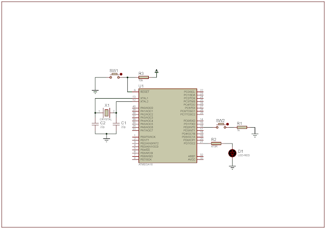
Atmega16 has up to 21 interrupt sources. Here I will discuss only the external interrupt of this controller. External interrupt consist of three source sources:
- INT0 - External interrupt request 0
- INT1 - External interrupt request 1, and
- INT2 - External interrupt request 2.
First I will show how to use INT0 source. It has four sense that determine whether the interrupt is triggering. It is the Interrupt Sense Control register bits of the MCU Control Register (MCUCR).
 |
| MCU Control Register (MCUCR) |
 |
| Interrupt Sense Control register bits |
The General Interrupt Control Register (GICR) turn on and off these external interrupt source, including the INT0 source.
 |
| General Interrupt Control Register – GICR |
They also have their corresponding interrupt flag in the General Interrupt Flag Control (GIFR).
 |
| General Interrupt Flag Control (GIFR) |
There are three bit corresponding to INTF1, INTF0, and INTF2. These bits will be cleared after the Interrupt Service Routine (ISR) executed. Optionally the programmer can clear any flag by setting it. However it is uncommon from most of microcontrollers.
In C programming the interrupt is very easy to program that I will show it in this programming example.
In this example I use only the INT0 source. The interrupt sense is the falling edge of INT0, as I will select it in program. Each time the INT0 occurs, and output LED connects to PD7 will toggle.
 |
| Schematic Diagram |
The source code is very simple. It contains a little lines of code.
Click here to download it source file.