Thursday, August 19, 2021

Arduino Analog Input and Display


Introduction

Arduino Uno has up to six analog input pins. Each analog inputs has resolution of 10-bit (0 – 1023). By default its reference voltage is 5V.

Within this example, we use analog reading on A0 and show its voltage level on seven segment display.

Arduino Analog Input and Display
Schematic Diagram
 

Arduino Programming

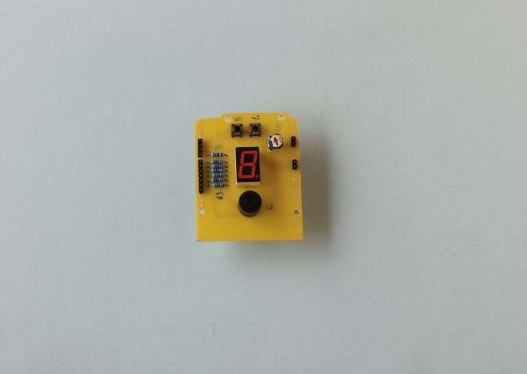
Arduino analogRead() function perform an analog voltage reading on any analog pin ranges from A0 to A5. Here we use A0 pin to read input voltage. We use a DIY Arduino shield for this example.

/* Main.ino file generated by New Project wizard
*
* Created: Tue Dec 4 2018
* Processor: Arduino Uno
* Compiler: Arduino AVR
*/
#define POT A0
#define BUZ 6
char ssd[10]={0x3F,0x06,0x5B,0x4F,0x66,0x6D,0x7D,0x07,0x7F,0x6F};
int cnt=0;
void displays(char cnt){
digitalWrite(7,bitRead(ssd[cnt],0));
digitalWrite(8,bitRead(ssd[cnt],1));
digitalWrite(9,bitRead(ssd[cnt],2));
digitalWrite(10,bitRead(ssd[cnt],3));
digitalWrite(11,bitRead(ssd[cnt],4));
digitalWrite(12,bitRead(ssd[cnt],6));
digitalWrite(13,bitRead(ssd[cnt],5));
}
void setup()
{ // put your setup code here, to run once:
pinMode(7,OUTPUT);
pinMode(8,OUTPUT);
pinMode(9,OUTPUT);
pinMode(10,OUTPUT);
pinMode(11,OUTPUT);
pinMode(12,OUTPUT);
pinMode(13,OUTPUT);
pinMode(BUZ,OUTPUT);
}
void loop()
{ // put your main code here, to run repeatedly:
int readA0=analogRead(POT);
delay(100);
cnt=(float)readA0*5.0/1023;
if(cnt>3) digitalWrite(BUZ,HIGH);
else digitalWrite(BUZ,LOW);
displays(cnt);
}


Click here to download this example package.


Wednesday, August 18, 2021

A DIY Arduino Analog and Digital I/O Shield


Introduction

A TWI devices shield for Arduino was listed in previous post. In this post I show only a simple digital input/output shield for Arduino Uno.

A DIY Arduino Analog and Digital I/O Shield
Finished assembling of this shield
It contains only a single red common cathode display in a size of 0.56″, Two push buttons for digital inputs, an active buzzer, and an analog input pin made of from a POT.

However this stuff can be easily hook up on a single breadboard. I made it because of free time and components stocking.

Copper Board Design of Arduino Shield

It’s not necessary to draw a schematic diagram for this board. All component’s connections are easily seen on Arduino Uno board.

A DIY Arduino Analog and Digital I/O Shield
Diagram of this Arduino Uno shield

Analog Input

A 100kOhm variable resistor or POT placed on board to connect to pin A0 of the Arduino Uno. It varies the input voltage between 0 to +5V.

Digital Inputs

Two tactile switches connect to digital pin 4 and 5 of Arduino Uno. They don’t have any external pull up resistors because the programmer can pull them high in program.

Digital Outputs


A single red common cathode seven-segment display connect between pin 7 to 13 of the Arduino Uno. It’s already have its current limiting resistors to make it work safe.

An active buzzer connects pin 6 of the Arduino Uno. Since the output current of Arduino Uno digital pin is up to 40mA, it no need to be driven from a transistor.

Copper Circuit Pattern

This circuit board was design in Proteus 8.x using its built-in Arduino Uno board template.

A DIY Arduino Analog and Digital I/O Shield
PCB design view in software

Using toner-transfer-method can make this PCB easily done.


A DIY Arduino Analog and Digital I/O Shield
Copper layer soldering side

Top side may ignored to printed it on board panel.

A DIY Arduino Analog and Digital I/O Shield
Top components silk screen side

Click here to download zip file of this light-weighted PCB project.

A DIY Arduino Analog and Digital I/O Shield
Top component layer


A DIY Arduino Analog and Digital I/O Shield
Bottom copper soldering layer

DIY PIC18F4550 USB Prototype Board

DIY PIC18F4550 USB Prototype Board
Prototype Board for PIC18F4550 and other 8-bit 40-Pin PIC Microcontroller Experiment Board for Hobbyists

Labels