Introduction
A fundamental timer/counter module usually come with an 8-bit microcontroller. It's a set of registers composing of a free running counter with its operating control registers, and its interrupt flag.
This microcontroller inside's module has two operating modes - timer and counter mode. Timer mode is useful for creating a precise timing delay, measuring duration of incoming external pulse, etc. Counter mode store a numbers of external incoming input pulse.
PIC16F887 Timer0 Module
As it's mentioned earlier, this module could work in two modes. PIC16F887 Timer0 module is in similar way with some additional features:
- Switching between timer and counter mode
- Prescaler selection bit for both modes
- Interrupt control
- Clock edge selection for counter mode
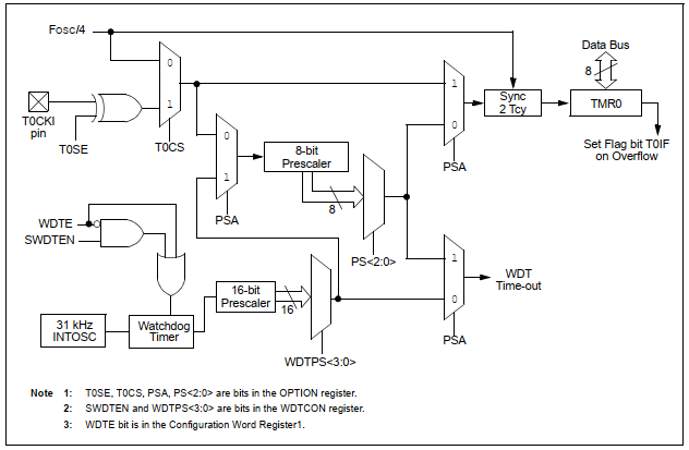 |
| Timer/WDT Prescaler Block Diagram |
Registers
Four registers of SFR relates to this module.
 |
| Summary of registers relate to Timer0 |
Timer0 register TMR0 is an 8-bit register for both timer and counter mode. If overflows at the top (255 or 0xFF in hexadecimal) and rolls back to bottom ( zero ) at the moment its interrupt flag is set.
Interrupt Control Register (INTCON) handles interrupt programming relates to Timer0 module (for both modes). In this post we don't discuss more about it.
Option Register OPTION_REG configures the operation for both modes. It includes prescaler selection, clock edge selection, and switching between timer and counter mode.
Switching Timer0 to Counter Mode
In this section OPTION_REG configures the process of this module.
TMR0 Clock Clock Select bits (T0CS) select input clock edge in counter mode. Setting it to select falling edge of input pulse.
Prescaler Assignment bit (PSA) switches between Watch Dog Timer (WDT) and Timer module. Set it to assign prescaler selection to WDT.
Prescaler Rate Select bits (PS<2:0>) adjust its input rate between 1:1 and 1:256.
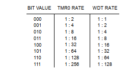 | |
| Prescaler Rate Select bits of OPTION_REG |
In counter mode RA4/T0CKI pin of Port A must configured to digital input to count external input pulse.
Counter Mode Programming in MikroC
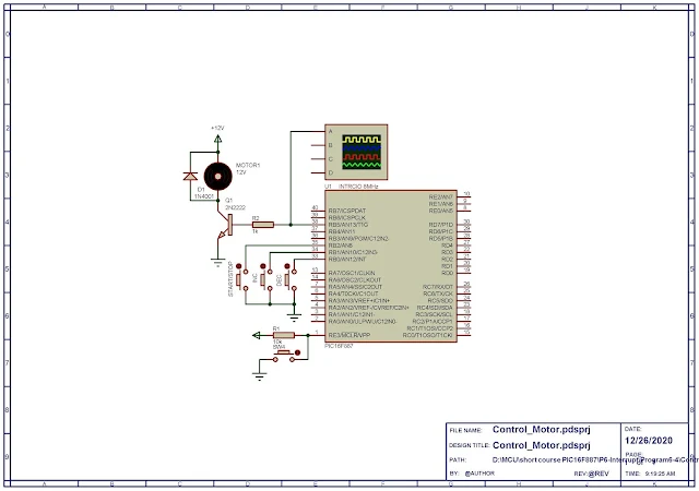
In this programming example, the controller works in counter mode showing counting value on a single 7-Segments display. The display shows up to 16 counts.
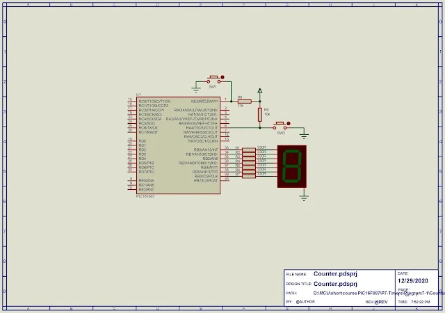 |
| Schematic Diagram |
Its internal 8MHz oscillator frequency is used here.
*****************************************************************************
Click here to download source file.
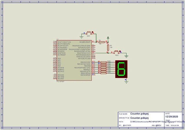 |
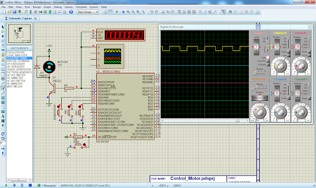
| Program simulation |
