Pages

Monday, January 29, 2024

XC95108 16-bit Serial In Parallel Out Shift Registers VHDL Example

A Serial-In-Parallel-Out shift register IC is very popular among micro-controller programmers. It's commonly use for I/O extending, LED driving, relay driving, etc. The SN75C595N or the SN74HC164 are commonly used with micro-controllers to expand their outputs.
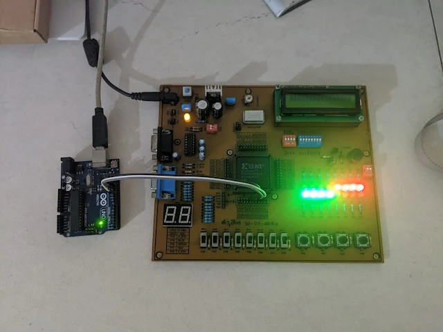
XC95108 16-bit Serial In Parallel Out Shift Registers VHDL Example
Hardware test on bread-board with Arduino Uno SPI

Using a CPLD/FPGA we can create any digital circuit including this type shift registers chip. In this example, I use the XC95108 CPLD to create a 16-bit serial in parallel out shift registers chip. The chosen language is VHDL.

The designed chip include reset(RST), serial clock(CLK), and serial data in (DIN). Its output is an 16-bit output port connects to LED.

  1. ----------------------------------------------------------------------------------
  2. -- Company:
  3. -- Engineer:
  4. --
  5. -- Create Date: 10:34:09 01/29/2024
  6. -- Design Name:
  7. -- Module Name: shift_regs_16_LED - Behavioral
  8. -- Project Name:
  9. -- Target Devices:
  10. -- Tool versions:
  11. -- Description:
  12. --
  13. -- Dependencies:
  14. --
  15. -- Revision:
  16. -- Revision 0.01 - File Created
  17. -- Additional Comments:
  18. --
  19. ----------------------------------------------------------------------------------
  20. library IEEE;
  21. use IEEE.STD_LOGIC_1164.ALL;
  22.  
  23. -- Uncomment the following library declaration if using
  24. -- arithmetic functions with Signed or Unsigned values
  25. --use IEEE.NUMERIC_STD.ALL;
  26.  
  27. -- Uncomment the following library declaration if instantiating
  28. -- any Xilinx primitives in this code.
  29. --library UNISIM;
  30. --use UNISIM.VComponents.all;
  31.  
  32. entity shift_regs_16_LED is
  33. Port ( CLK : in STD_LOGIC;
  34. RST : in STD_LOGIC;
  35. DIN : in STD_LOGIC;
  36. LEDS : out STD_LOGIC_VECTOR (15 downto 0));
  37. end shift_regs_16_LED;
  38.  
  39. architecture Behavioral of shift_regs_16_LED is
  40. SIGNAL REGS: STD_LOGIC_VECTOR(15 DOWNTO 0);
  41. begin
  42. PROCESS(CLK,RST)
  43. BEGIN
  44. IF(RST='0') THEN REGS<=x"0000";
  45. ELSIF(CLK'EVENT AND CLK='1') THEN
  46. REGS(0)<=DIN;
  47. REGS(1)<=REGS(0);
  48. REGS(2)<=REGS(1);
  49. REGS(3)<=REGS(2);
  50. REGS(4)<=REGS(3);
  51. REGS(5)<=REGS(4);
  52. REGS(6)<=REGS(5);
  53. REGS(7)<=REGS(6);
  54. REGS(8)<=REGS(7);
  55. REGS(9)<=REGS(8);
  56. REGS(10)<=REGS(9);
  57. REGS(11)<=REGS(10);
  58. REGS(12)<=REGS(11);
  59. REGS(13)<=REGS(12);
  60. REGS(14)<=REGS(13);
  61. REGS(15)<=REGS(14);
  62. END IF;
  63. LEDS<=REGS;
  64. END PROCESS;
  65.  
  66. end Behavioral;
  67.  
  68.  

Its internal circuit doesn't need additional clock input to synchronize input data. The data is synchronized with serial clock pin from external device.

Its I/O pins are assigned as follow using the Floorplan I/O tool.

  1. #PACE: Start of Constraints generated by PACE
  2.  
  3. #PACE: Start of PACE I/O Pin Assignments
  4. NET "CLK" LOC = "P48" ;
  5. NET "DIN" LOC = "P50" ;
  6. NET "LEDS<0>" LOC = "P63" ;
  7. NET "LEDS<10>" LOC = "P67" ;
  8. NET "LEDS<11>" LOC = "P68" ;
  9. NET "LEDS<12>" LOC = "P69" ;
  10. NET "LEDS<13>" LOC = "P70" ;
  11. NET "LEDS<14>" LOC = "P71" ;
  12. NET "LEDS<15>" LOC = "P72" ;
  13. NET "LEDS<1>" LOC = "P62" ;
  14. NET "LEDS<2>" LOC = "P61" ;
  15. NET "LEDS<3>" LOC = "P58" ;
  16. NET "LEDS<4>" LOC = "P57" ;
  17. NET "LEDS<5>" LOC = "P56" ;
  18. NET "LEDS<6>" LOC = "P55" ;
  19. NET "LEDS<7>" LOC = "P54" ;
  20. NET "LEDS<8>" LOC = "P65" ;
  21. NET "LEDS<9>" LOC = "P66" ;
  22. NET "RST" LOC = "P47" ;
  23.  
  24. #PACE: Start of PACE Area Constraints
  25.  
  26. #PACE: Start of PACE Prohibit Constraints
  27.  
  28. #PACE: End of Constraints generated by PACE
  29.  

After the design and programming process are completed, we can test this circuit manually with a few on-board input switches. For convenience we can use a popular Arduino Uno as an SPI master device transferring a 16-bit data to this shift registers chip.

  1. #include<SPI.h>
  2.  
  3. void setup() {
  4. SPI.begin();
  5. }
  6.  
  7. char data[2];
  8. void loop() {
  9. data[0]=0xF0;
  10. data[1]=0x0F;
  11. SPI.transfer(data,2);
  12. delay(1000);
  13. data[0]=0x0F;
  14. data[1]=0xF0;
  15. SPI.transfer(data,2);
  16. delay(1000);
  17. }

The circuit connections between the Arduino Uno and the XC95108 CPLD are:

Arduino Uno            XC95108 CPLD Prototype Board

GND                        GND

PIN11 (MOSI)            P50

PIN13 (SCK)               P48

I use the Arduino SPI module and library without bit-banging. Optionally we can use the on-board 7-Segment display instead of the LED.

Click here to download its source file.

No comments:

Post a Comment