Pages

Friday, December 8, 2023

XC9536 CPLD LED Chasing Using VHDL

In this VHDL Example, I use ROL (Rotate Left) and ROR (Rotate Right) operators to chase the LEDs left or right. An input switch determines its chasing direction. A frequency divider is added to get a lower frequency driven from a NE555 square wave oscillator.

XC9536 CPLD Rotates LED Using VHDL
CPLD Hardware Test


VHDL source is quite simple due to the rotate operators.

  1. ----------------------------------------------------------------------------------
  2. -- Company:
  3. -- Engineer:
  4. --
  5. -- Create Date: 14:35:50 12/08/2023
  6. -- Design Name:
  7. -- Module Name: LED_ROTATE - Behavioral
  8. -- Project Name:
  9. -- Target Devices:
  10. -- Tool versions:
  11. -- Description:
  12. --
  13. -- Dependencies:
  14. --
  15. -- Revision:
  16. -- Revision 0.01 - File Created
  17. -- Additional Comments:
  18. --
  19. ----------------------------------------------------------------------------------
  20. library IEEE;
  21. use IEEE.STD_LOGIC_1164.ALL;
  22.  
  23. -- Uncomment the following library declaration if using
  24. -- arithmetic functions with Signed or Unsigned values
  25. --use IEEE.NUMERIC_STD.ALL;
  26.  
  27. -- Uncomment the following library declaration if instantiating
  28. -- any Xilinx primitives in this code.
  29. --library UNISIM;
  30. --use UNISIM.VComponents.all;
  31.  
  32. entity LED_ROTATE is
  33. Port ( CLK : in STD_LOGIC;
  34. SEL : in STD_LOGIC;
  35. LED : out BIT_VECTOR (7 downto 0));
  36. end LED_ROTATE;
  37.  
  38. architecture Behavioral of LED_ROTATE is
  39.  
  40. signal tmp : BIT_VECTOR(7 DOWNTO 0) :=X"01";
  41.  
  42. begin
  43.  
  44. process(CLK,SEL)
  45. variable count : INTEGER RANGE 0 TO 9;
  46. begin
  47. if(clk'event and clk = '1') then
  48. count:=count+1;
  49. if(count=9) then
  50. if(sel='0') then tmp<=tmp ROL 1;
  51. else tmp<=tmp ROR 1;
  52. end if;
  53. end if;
  54. LED<=tmp;
  55. end if;
  56. end process;
  57. end Behavioral;
  58.  
  59.  

I assign all the I/O pin as follow.

#PACE: Start of Constraints generated by PACE
#PACE: Start of PACE I/O Pin Assignments
NET "CLK"  LOC = "P5"  ; 
NET "LED<0>"  LOC = "P40"  ; 
NET "LED<1>"  LOC = "P39"  ; 
NET "LED<2>"  LOC = "P38"  ; 
NET "LED<3>"  LOC = "P37"  ; 
NET "LED<4>"  LOC = "P36"  ; 
NET "LED<5>"  LOC = "P35"  ; 
NET "LED<6>"  LOC = "P34"  ; 
NET "LED<7>"  LOC = "P33"  ; 
NET "SEL"  LOC = "P25"  ;
#PACE: Start of PACE Area Constraints
#PACE: Start of PACE Prohibit Constraints
#PACE: End of Constraints generated by PACE

Each I/O device are already placed on the XC9536 CPLD Test Board.

Its RTL schematic is shown below.
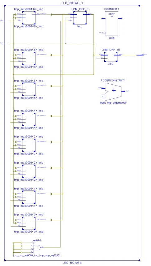
XC9536 CPLD Rotates LED Using VHDL
RTL

I use a Xilinx Parallel Cable III to program this CPLD.

XC9536 CPLD Rotates LED Using VHDL
iMPACT Device Programming Using Parallel Cable III

It still work on a Desktop PC operated by Microsoft Windows 10.


Click here to download its source file.

No comments:

Post a Comment